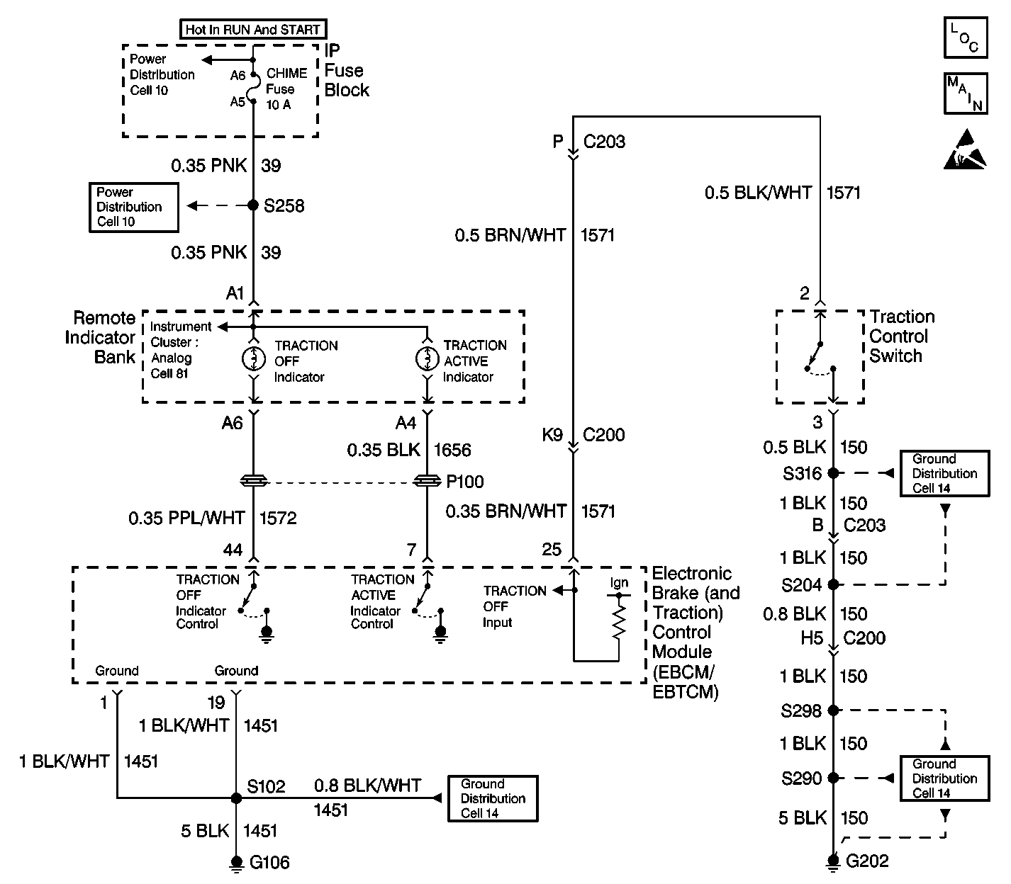
Traction Off Indicator Inoperative Oldsmobile

Circuit Description
The EBTCM goes through a self-test when the ignition is first turned to RUN. During this test, the EBTCM grounds both the ANTILOCK and the TRACTION OFF indicators for 2 to 4 seconds. This acts as a bulb test for the indicators.
Traction Control Switch
The traction control switch allows the driver to select the traction control mode (ON/OFF). When the Traction Control System is turned OFF, the TRACTION OFF indicator remains illuminated.
Diagnostic Aids
The following conditions may cause the TRACTION OFF indicator to be inoperative:
| • | An open fuse |
| • | An open bulb |
| • | An open in any of the following circuits: |
| - | CKT 39 |
| - | CKT 150 |
| - | CKT 1451 |
| - | CKT 1571 |
| - | CKT 1572 |
| • | A malfunction instrument cluster |
| • | A malfunctioning traction control switch |
When the vehicle is equipped with traction control any symptom that illuminates the ANTILOCK indicator also illuminates the TRACTION OFF indicator. Follow the ANTILOCK indicator diagnosis when both indicators are illuminated and no DTCs are set.
Step | Action | Value(s) | Yes | No |
|---|---|---|---|---|
1 | Was the ABS Diagnostic System Check performed? | -- | Go to Step 2 | |
2 | Turn the ignition switch to the RUN position. Does the TRACTION OFF indicator come ON for 2-4 seconds? | -- | Go to Step 3 | Go to Step 9 |
3 |
Is the voltage within the specified range? | Battery Voltage | Go to Step 4 | Go to Step 6 |
4 |
Is the resistance less than the specified value? | 2 ohms | Go to Step 5 | Go to Step 15 |
5 |
Is the repair complete? | -- | -- | |
6 |
Is the resistance less than the specified value? | 2 ohms | Go to Step 8 | Go to Step 7 |
7 | Repair the open or high resistance in CKT 1571. Refer to Wiring Repairs in Wiring Systems. Is the repair complete? | -- | -- | |
8 |
Is the repair complete? | -- | -- | |
9 |
Is the voltage less than the specified value? | Battery Voltage | Go to Step 10 | Go to Step 12 |
10 |
Is the voltage less than the specified value? | Battery Voltage | Go to Step 11 | Go to Step 13 |
11 |
Is the voltage less than the specified value? | Battery Voltage | Go to Step 16 | Go to Step 14 |
12 | Repair the open or high resistance in CKT 39. Refer to Wiring Repairs in Wiring Systems. Is the repair complete? | -- | -- | |
13 | Repair the open or high resistance in CKT 1451. Refer to Wiring Repairs in Wiring Systems. Is the repair complete? | -- | -- | |
14 | Repair the open or high resistance in CKT 1572. Refer to Wiring Repairs in Wiring Systems. Is the repair complete? | -- | -- | |
15 | Repair the open or high resistance in CKT 150. Refer to Wiring Repairs in Wiring Systems. Is the repair complete? | -- | -- | |
16 | Replace the ANTILOCK indicator bulb. Refer to Instrument Cluster Replacement in Instrument Panel, Gauges and Console. Is the repair complete? | -- | -- |
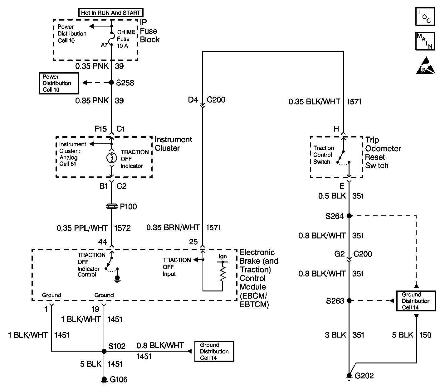
Traction Off Indicator Inoperative Buick

Circuit Description
The EBTCM goes through a self-test when the ignition is first turned to RUN. During this test, the EBTCM grounds both the ANTILOCK and the TRACTION OFF indicators for 2 to 4 seconds. This acts as a bulb test for the indicators.
Traction Control Switch
The traction control switch allows the driver to select the traction control mode (ON/OFF). When the Traction Control System is turned OFF, the TRACTION OFF indicator remains illuminated.
Diagnostic Aids
The following conditions may cause the TRACTION OFF indicator to be inoperative:
| • | An open fuse |
| • | An open bulb |
| • | An open in any of the following circuits: |
| - | CKT 39 |
| - | CKT 150 |
| - | CKT 1451 |
| - | CKT 1571 |
| - | CKT 1572 |
| • | A malfunction instrument cluster |
| • | A malfunctioning traction control switch |
When the vehicle is equipped with traction control any symptom that illuminates the ANTILOCK indicator also illuminates the TRACTION OFF indicator. Follow the ANTILOCK indicator diagnosis when both indicators are illuminated and no DTCs are set.
Step | Action | Value(s) | Yes | No |
|---|---|---|---|---|
1 | Was the ABS Diagnostic System Check performed? | -- | Go to Step 2 | |
2 | Turn the ignition switch to the RUN position. Does the TRACTION OFF indicator come ON for 2-4 seconds? | -- | Go to Step 3 | Go to Step 9 |
3 |
Is the voltage within the specified range? | Battery Voltage | Go to Step 4 | Go to Step 6 |
4 |
Is the resistance less than the specified value? | 2 ohms | Go to Step 5 | Go to Step 15 |
5 |
Is the repair complete? | -- | -- | |
6 |
Is the resistance less than the specified value? | 2 ohms | Go to Step 8 | Go to Step 7 |
7 | Repair the open or high resistance in CKT 1571. Refer to Wiring Repairs in Wiring Systems. Is the repair complete? | -- | -- | |
8 |
Is the repair complete? | -- | -- | |
9 |
Is the voltage less than the specified value? | Battery Voltage | Go to Step 10 | Go to Step 12 |
10 |
Is the voltage less than the specified value? | Battery Voltage | Go to Step 11 | Go to Step 13 |
11 |
Is the voltage less than the specified value? | Battery Voltage | Go to Step 16 | Go to Step 14 |
12 | Repair the open or high resistance in CKT 39. Refer to Wiring Repairs in Wiring Systems. Is the repair complete? | -- | -- | |
13 | Repair the open or high resistance in CKT 1451. Refer to Wiring Repairs in Wiring Systems. Is the repair complete? | -- | -- | |
14 | Repair the open or high resistance in CKT 1572. Refer to Wiring Repairs in Wiring Systems. Is the repair complete? | -- | -- | |
15 | Repair the open or high resistance in CKT 351. Refer to Wiring Repairs in Wiring Systems. Is the repair complete? | -- | -- | |
16 | Replace the ANTILOCK indicator bulb. Refer to Instrument Cluster Replacement in Instrument Panel, Gauges and Console. Is the repair complete? | -- | -- |
