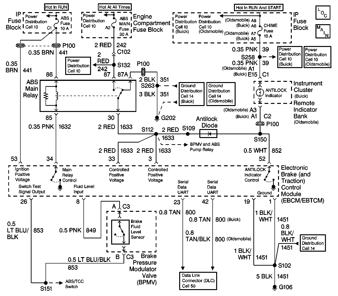
Circuit Description
When the ignition is first turned to RUN, the EBCM/EBTCM goes through a self-test which lasts 2 to 4 seconds.
During the test, the EBCM/EBTCM grounds terminal 52. This causes the amber ANTILOCK indicator to light. This serves as an indicator bulb test.
When the fluid is low, the EBCM/EBTCM turns ON the amber ANTILOCK and TRACTION OFF indicators. The EBCM/EBTCM does not set a DTC.
A low fluid level condition usually lights the red BRAKE warning lamp, since the master cylinder supplies the BPMV reservoir. However, restrictions or air in the hose could cause a low fluid condition in the BPMV reservoir without lighting the red BRAKE warning lamp.
Diagnostic Aids
The following conditions may cause the ANTILOCK indicator to be on with no DTCs set:
| • | An open in any of the following circuits: |
| - | CKT 441 |
| - | CKT 800 |
| - | CKT 1451 |
| - | CKT 849 |
| - | CKT 853 |
| • | A low brake fluid level |
| • | An open BPMV fluid level switch circuit |
| • | A short to ground in any of the following circuits: |
| - | CKT 441 |
| - | CKT 800 |
| - | CKT 852 |
Step | Action | Value(s) | Yes | No | ||||||
|---|---|---|---|---|---|---|---|---|---|---|
1 | Was the ABS Diagnostic System Check performed? | -- | Go to Step 2 | |||||||
2 |
Is the fuse open? | -- | Go to Step 10 | Go to Step 3 | ||||||
3 |
If the fluid is low, check for leaks, kinks, or restrictions. Add fluid as needed to the master cylinder reservoir. Refer to Master Cylinder Reservoir Filling in Hydraulic Brakes. Is the resistance less than the specified value? | 1 ohms | Go to Step 4 | Go to Step 11 | ||||||
4 |
Is the resistance less than the specified value? | 2 ohms | Go to Step 5 | Go to Step 12 | ||||||
5 |
Is the resistance less than the specified value? | 2 ohms | Go to Step 6 | Go to Step 13 | ||||||
6 |
Is the voltage within the specified range? | Battery Voltage | Go to Step 7 | Go to Step 14 | ||||||
7 |
Is the voltage within the specified range? | Battery Voltage | Go to Step 8 | Go to Step 15 | ||||||
8 | Check the EBCM/EBTCM connector and wiring for the following conditions:
Is there corrosion or damage to the connector and/or wiring? | -- | Go to Step 16 | Go to Step 9 | ||||||
9 | Replace the EBCM/EBTCM. Refer to Electronic Brake and Traction Control Module Replacement . Is the repair complete? | -- | -- | |||||||
10 | Repair the short to ground in CKT 441. Refer to Wiring Repairs in Wiring Systems. Is the repair complete? | -- | -- | |||||||
11 | Replace the BPMV reservoir. Refer to Brake Pressure Module Valve Reservoir Replacement . Is the repair complete? | -- | -- | |||||||
12 | Repair the open or high resistance in CKT 849 or CKT 853. Refer to Wiring Repairs in Wiring Systems. Is the repair complete? | -- | -- | |||||||
13 | Repair the open or high resistance in CKT 1451 or G106. Refer to Wiring Repairs in Wiring Systems. Is the repair complete? | -- | -- | |||||||
14 | Repair the open or high resistance in CKT 441. Refer to Wiring Repairs in Wiring Systems. Is the repair complete? | -- | -- | |||||||
15 | Repair the short to ground in CKT 852. Refer to Wiring Repairs in Wiring Systems. Is the repair complete? | -- | -- | |||||||
16 |
Is the repair complete? | -- | -- |
