For 1990-2009 cars only
Steering Wheel Control Switch Assembly Replacement Buick
Removal Procedure
- Disable the SIR system. Refer to Disabling the SIR System in Restraints.
- Remove the inflatable restraint steering wheel module. Refer to Inflatable Restraint Steering Wheel Module Replacement in Restraints .
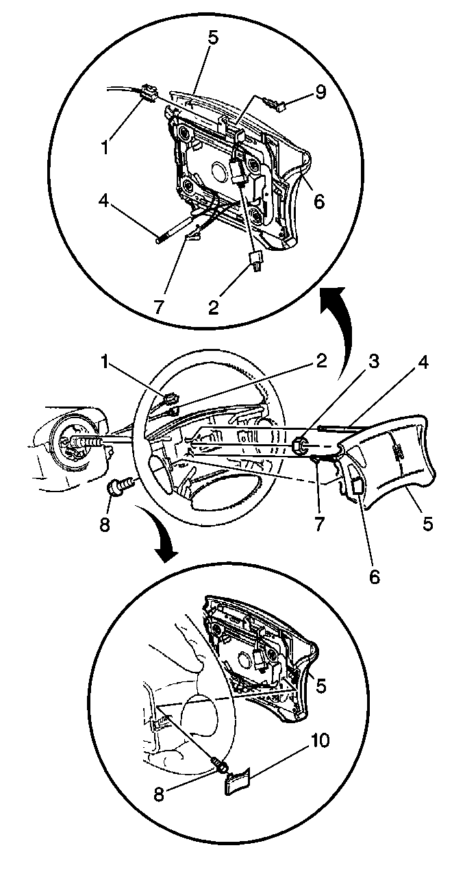
- Remove two screws (8) from each side of the control switch assembly (6).
- Disconnect the control switch assembly (6) from the inflator module (5).
- Disconnect the following components from the inflator module (5):

Important: Service the steering wheel control switches (6) and the connector (2) as an assembly.
Important: Service the horn ground lead (7) and the contact lead (4) as an assembly.
| • | The horn ground lead (7) |
| • | The contact lead (4) |
Installation Procedure
- Connect the following components to the inflator module (5):
- Align the control switch assembly (6) into place.
- Secure the control switch assembly with two screws (8) on each side.
- Install the inflatable restraint steering wheel module . Refer to Inflatable Restraint Steering Wheel Module Replacement in Restraints .
- Enable the SIR system. Refer to Enabling the SIR System in Restraints.

| • | The horn ground lead (7) |
| • | The contact lead (4) |
Steering Wheel Control Switch Assembly Replacement Oldsmobile
Removal Procedure
- Disable the SIR system. Refer to Disabling the SIR System in Restraints.
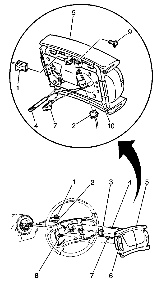
- Remove the inflatable restraint steering wheel module (5). Refer to Inflatable Restraint Steering Wheel Module Replacement in Restraints .
- Remove the protector plate (10) from the inflator module.
- Remove the four screws (8) from the inflator module (5).
- Remove two screws (8) from each side of the control switch assembly (6).
- Disconnect the control switch assembly (6) from the protector plate (5).
- Disconnect the horn ground lead (7) and the contact lead (4) from the inflator module (5).

Important: Service the steering wheel control switches (6) and the connector (2) as an assembly.
Important: Service horn ground lead (7) and the contact lead (4) as an assembly.
Installation Procedure
- Connect the horn ground lead (7) and the contact lead (4) to the inflator module (5).
- Align the control switch assembly (6) into place. Secure the control switch assembly (6) with two screws (8) on each side.
- Install the protector plate (10) to the inflator module (5).
- Secure the protector plate (10) to the inflator module (5) with the four screws (8).
- Install the inflatable restraint steering wheel module . Refer to Inflatable Restraint Steering Wheel Module Replacement
- Enable the SIR system. Refer to Enabling the SIR System in Restraints.

