Removal Procedure
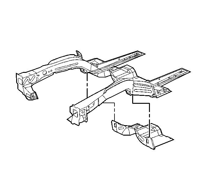
Replacement of the engine compartment lower rail assemblies has been improved through the use of a sub-assembly service part. Use of the sub-assembly service part simplifies the ordering, the stocking and the replacement procedures. The lower rail service part comes as a complete assembly, including all the brackets and the reinforcements. Replace the bumper mounting brackets separately.
- Disconnect the engine and the transmission. Support the engine and the transmission with suitable equipment.
- Remove all the other related panels and the components, including the suspension and the crossmember.
- Inspect for damage.
- Repair the damage as possible to the factory specifications.
- Remove the following components as necessary:
- Locate , mark and drill out the factory welds securing the front suspension support to the lower rail. Note the number of welds for installation of the service assembly.
- Locate, mark and drill out the factory welds along the lower flanges of the rail securing it to the cowl.
- Separate the lower rail from the floor extensions in the torque box area.
- Locate, mark and drill out all remaining factory welds.
- Remove the damaged front lower rail. If the front suspension support is not removed, the damaged rail must be pried out.

| • | The sealers |
| • | The sound deadeners |
| • | The corrosion materials |
Installation Procedure
- Prepare the mating surfaces.
- Inspect for the proper fit of the lower rail service assembly.
- On the service assembly, drill 8 mm (5/16 in) plug weld holes as necessary in the locations noted from the original parts.
- Position the service assembly.
- Inspect the fit of the service assembly using the body dimensions. Ensure the suspension support properly mates over the lower rail bracket.
- Plug the weld accordingly with frequent measurements in order to ensure proper fit.
- Clean the welded surfaces.
- Prepare the welded surfaces.
- Prime with two-part catalyzed primer.
- Apply the corrosion protection materials and the sealers, as necessary.
- Apply the dominion sure seal paintable sound deadening pads (part #110900) to the floor as necessary in order to match the original sound deadening.
- Reinstall the related panels and the components.
- Install the suspension crossmember.

Important: Prior to refinishing, refer to GM 4901MD-99 Refinish Manual for recommended products. Do not combine the paint systems. Refer to the paint manufacturer's recommendations. For further information or to order manual, call 1-800-269-5100.
Notice: Use the correct fastener in the correct location. Replacement fasteners must be the correct part number for that application. Fasteners requiring replacement or fasteners requiring the use of thread locking compound or sealant are identified in the service procedure. Do not use paints, lubricants, or corrosion inhibitors on fasteners or fastener joint surfaces unless specified. These coatings affect fastener torque and joint clamping force and may damage the fastener. Use the correct tightening sequence and specifications when installing fasteners in order to avoid damage to parts and systems.
Tighten
Tighten the fasteners to 130 N·m (96 lbs ft).
