SERVICE MANUAL UPDATE-SEC.10A2 POWER SEAT (DIAG./REPAIR INFO)

SUBJECT: POWER SEAT DIAGNOSIS AND REPAIR INFORMATION
MODEL/YEARS: 1993 BRAVADA
The following represents new information on the revised power seat that went into production on 1993 Bravadas beginning January 11, 1993, on VIN P2704650.
GENERAL DESCRIPTION
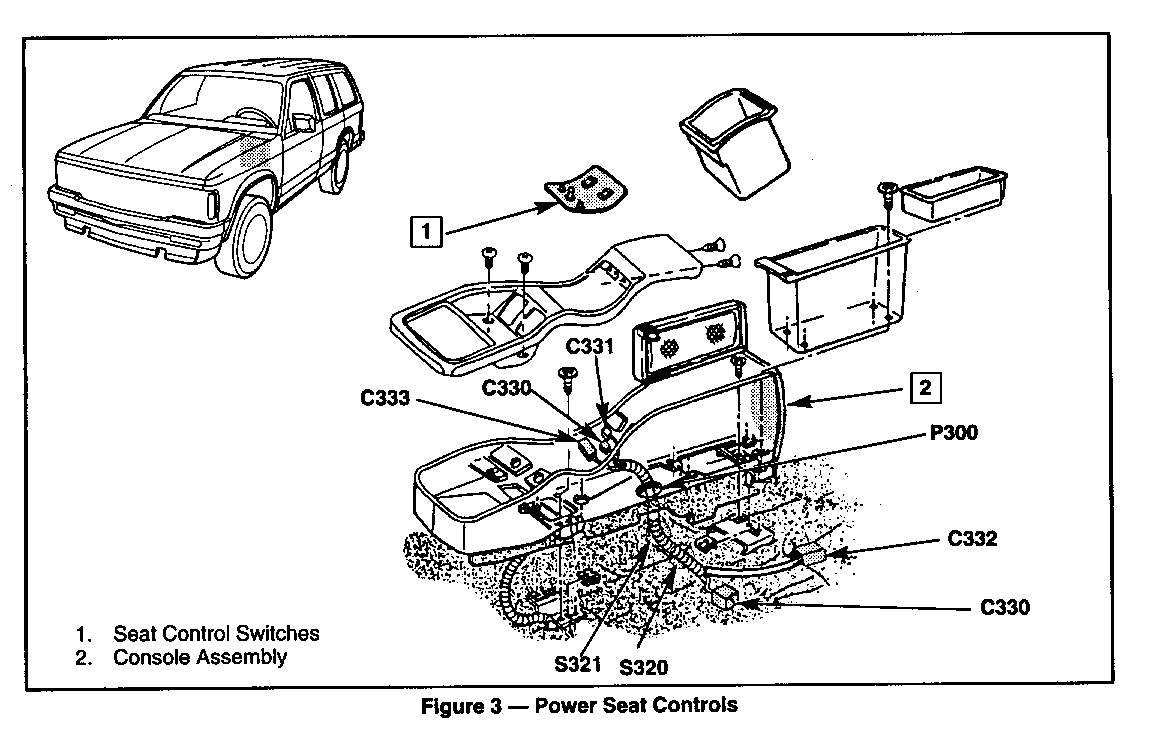
POWER SEAT: The power seat allows the driver to move the seat in six directions with an electric assist. An assembly consisting of three separate motors bolted to the seat adjuster and is driven by a series of gears that result in seat movement. Controls are located in the center console.
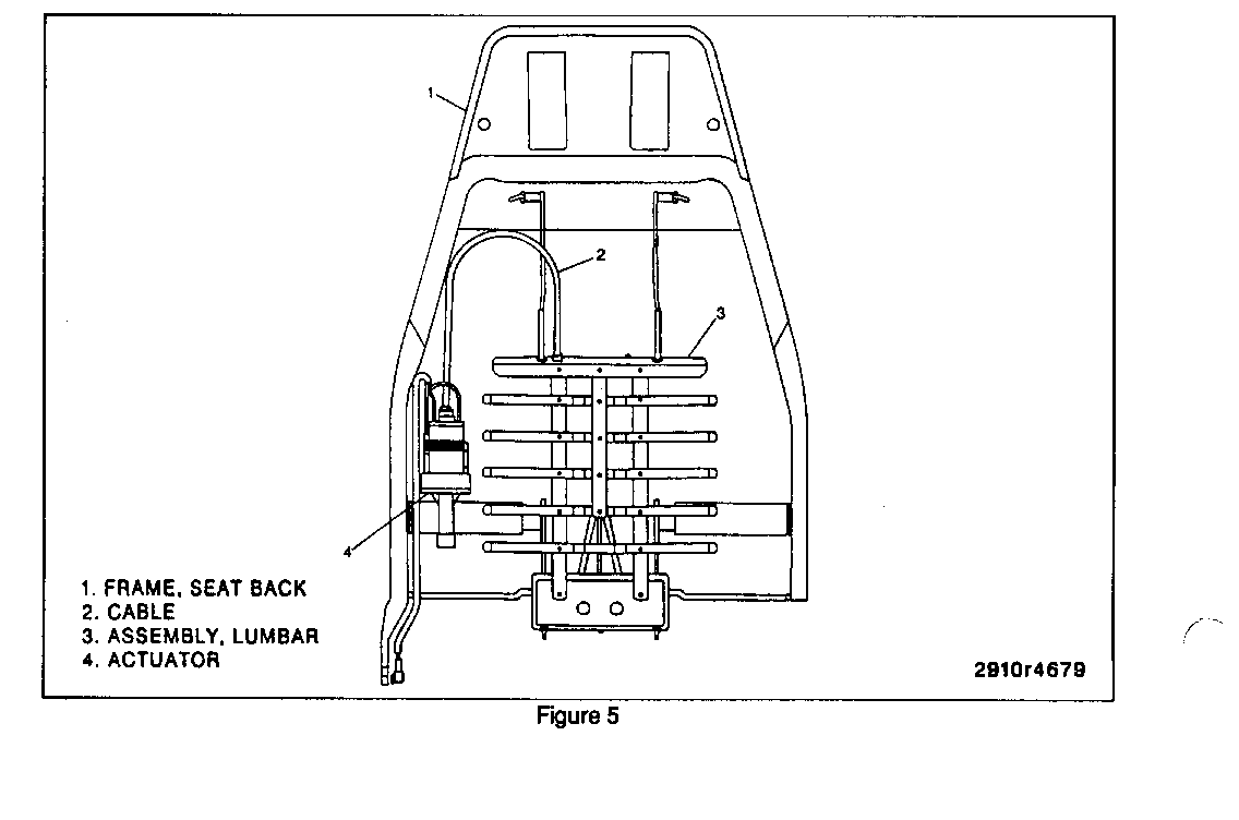
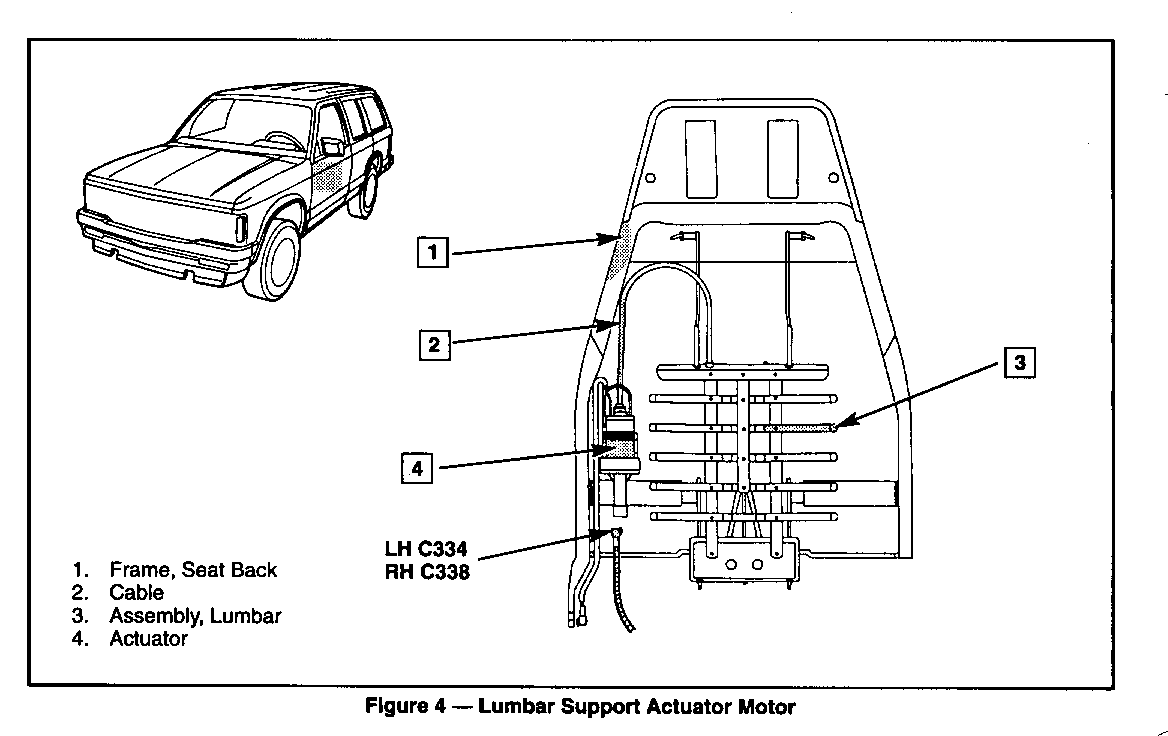
Both front seats are equipped with an electric lumbar adjustment feature. A two-way switch located in the center console directs current to the lumbar actuator, that is riveted to the seat back frame. The actuator receives input from the switch and acts through miniature gears and a drive cable to flex a metal grid. The grid can be flexed in and out, resulting in positive control of the shape of the lower seat back.
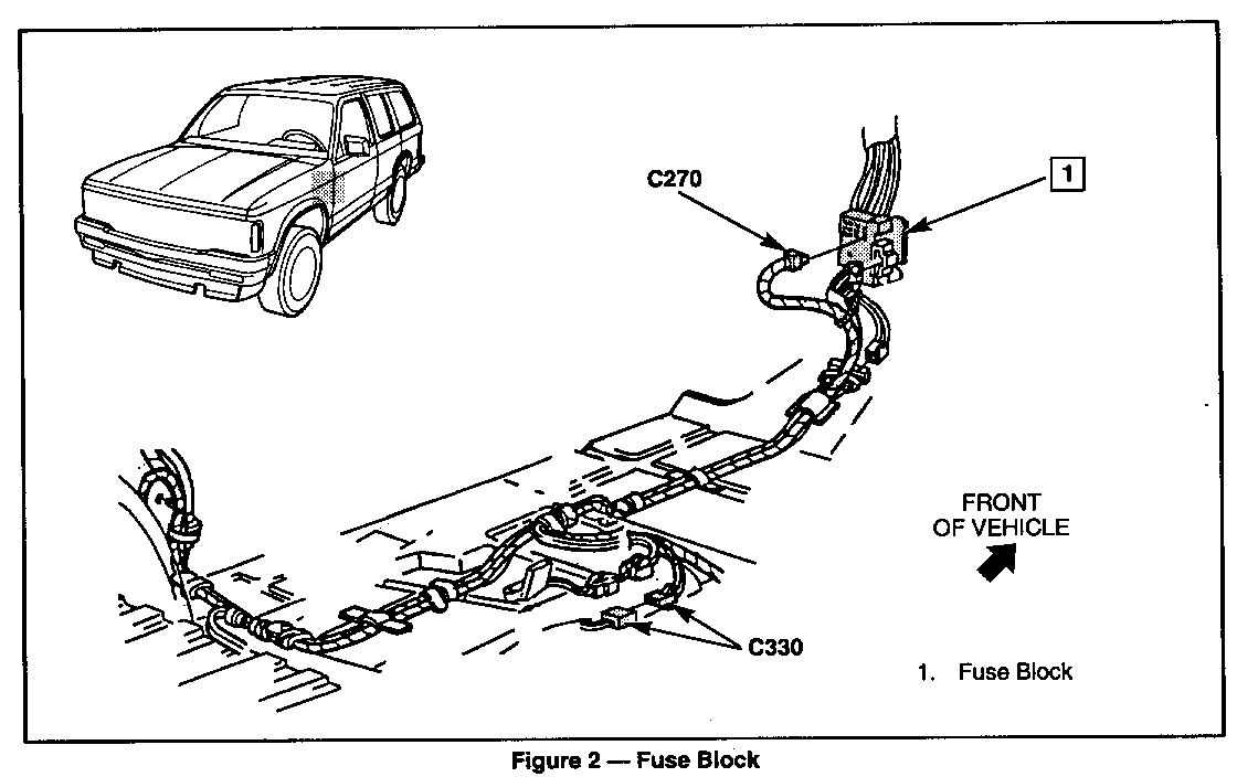
Power distribution for all seat functions starts at cavity E of the fuse block and travels through the cross body harness. Then it branches off and goes to the switches located in the center console.
DIAGNOSIS OF POWER SEAT:
* See pages 8A-140-1 through 8A-140-12 included in this bulletin.
ON-VEHICLE SERVICE
SEAT TRIM COVER REPLACEMENT
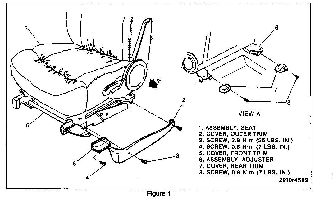
Remove Or Disconnect: (Figure 1) -------------------------------- 1. Outer seat trim cover screws.
2. Outer seat trim cover.
3. Front trim cover screw.
4. Front trim cover.
5. Rear trim cover screws.
o Move seat forward to gain access to the screws.
6. Rear trim covers.
Install Or Connect: (Figure 1) ------------------------------ Notice: For steps 2, 4, and 6, refer to "Notice" on page 10A2-1 of the 1993 Bravada Service Manual.
1. Rear trim covers.
2. Rear trim cover screws.
Tighten
o Rear trim cover screws to 0.8 N-m (7 lbs. in.).
3. Front seat trim cover.
4. Front seat trim cover screws.
Tighten
o Front seat trim cover screws to 0.8 N-m (7 lbs. in.).
5. Outer seat trim cover.
6. Outer seat trim cover screws.
Tighten
o Outer seat trim cover screws to 2.8 N-m (25 lbs. in.).
SEAT REPLACEMENT
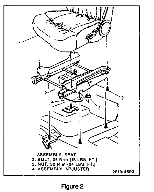
Remove Or Disconnect: (Figure 2) -------------------------------- 1. Negative battery cable. Refer to SECTION OA.
2. Seat trim cover screws.
3. Seat trim covers.
4. Seat adjuster to the seat bolts.
5. Electrical connections.
6. Seat from the vehicle.
Install Or Connect: (Figure 2) ------------------------------ 1. Seat to the vehicle.
2. Electrical connections.
Notice: Refer to "Notice" on page 10A2-1 of the 1993 Bravada Service Manual.
3. Seat adjuster to the seat bolts.
Tighten
o Seat adjuster to the seat nuts to 24 N-m (18 lbs. ft.).
4. Seat trim covers.
5. Seat trim cover screws.
6. Negative battery cable. Refer to SECTION OA of the 1993 Bravada Service Manual.
SEAT BACK REPLACEMENT
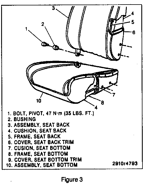
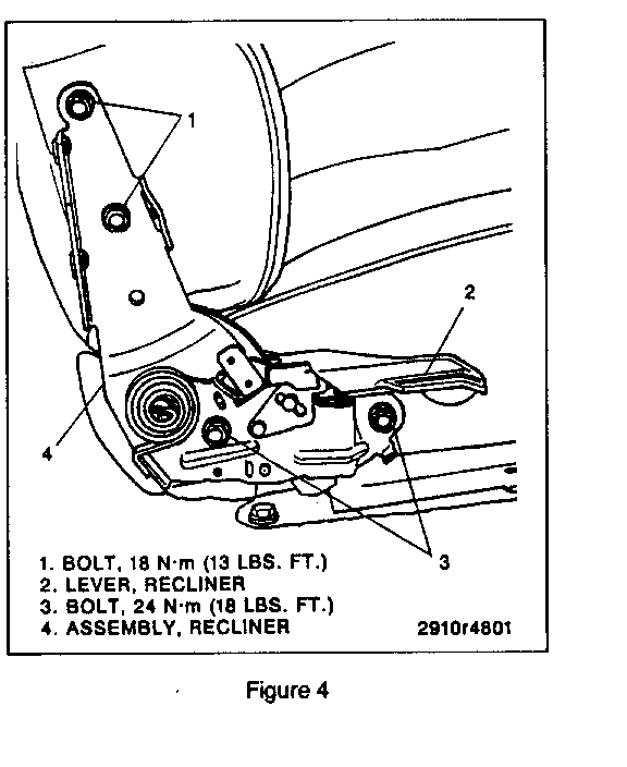
Remove Or Disconnect: (Figures 3 and 4) --------------------------------------- 1. Seat from the vehicle. Refer to "Seat Replacement".
2. Recliner assembly. Refer to "Manual Recliner Replacement".
3. Seat back pivot bolt and bushing.
4. Power lumbar connector.
5. Seat back from the lower frame.
Install Or Connect: (Figures 3 and 4) ------------------------------------- 1. Seat back to the lower frame.
2. Power lumbar connector.
Notice: Refer to "Notice" on page 10A2-1 the 1993 Bravada Service Manual.
3. Seat back pivot bolt and bushing.
Tighten
o Seat back pivot bolt to 47 N-m (35 lbs. ft.).
4. Recliner assembly. Refer to "Manual Recliner Replacement".
5. Seat to the vehicle. Refer to "Seat Replacement".
SEAT CUSHION REPLACEMENT
SEAT BACK CUSHION
Remove Or Disconnect: (Figure 3) -------------------------------- 1. Seat from the vehicle. Refer to "Seat Replacement".
2. Seat back. Refer to "Seat Back Replacement".
3. Seat back cover from the seat cushion.
o Unfasten seat back cover at the bottom and pull the cover from the seat.
4. Seat back cushion from the seat frame.
Install Or Connect: (Figure 3) ------------------------------ 1. Seat back cushion to the seat frame.
2. Seat back cover over the seat cushion.
3. Seat back. Refer to "Seat Back Replacement".
4. Seat to the vehicle. Refer to "Seat Replacement".
SEAT BOTTOM CUSHION
Remove Or Disconnect: (Figure 3) -------------------------------- 1. Seat from the vehicle. Refer to "Seat Replacement".
2. Seat back. Refer to "Seat Back Replacement".
3. Seat cover to the seat frame retaining rings.
4. Seat cover from the cushion.
5. Seat bottom cushion from the seat frame.
Install Or Connect: (Figure 3) ------------------------------ 1. Seat bottom cushion to the seat frame.
2. Seat cover over the seat cushion.
3. Seat cover to the seat frame with retaining rings.
4. Seat back. Refer to "Seat Back Replacement".
5. Seat to the vehicle. Refer to "Seat Replacement".
POWER LUMBAR REPLACEMENT
Important: * The lumbar adjuster is serviced as an assembly only.
Remove Or Disconnect: (Figure 5) -------------------------------- 1. Seat from the vehicle. Refer to "Seat Replacement".
2. Seat back. Refer to "Seat Back Replacement".
3. Seat back trim cover.
4. Seat back cushion. Refer to "Seat Cushion Replacement".
5. Drill out lumbar actuator to the seat back frame rivets.
6. Lumbar assembly from the seat back frame.
Install Or Connect: (Figure 5) ------------------------------ 1. Lumbar assembly to the seat back frame.
2. Actuator to the seat back frame with rivets.
3. Seat back cushion. Refer to "Seat Cushion Replacement".
4. Seat back trim cover.
5. Seat back. Refer to "Seat Back Replacement".
6. Seat to the vehicle. Refer to "Seat Replacement".
MANUAL RECLINER REPLACEMENT
Remove Or Disconnect: (Figure 4) -------------------------------- 1. Recliner trim cover screws.
2. Recliner trim covers from the seat.
3. Recliner assembly to the seat frame bolts.
4. Recliner assembly from the seat.
Install Or Connect: (Figure 4) -------------------------------- 1. Recliner assembly to the seat.
Notice: Refer to "Notice" on page 10A2-1 of the 1993 Bravada Service Manual.
2. Recliner assembly to the seat frame bolts.
Tighten
o Recliner assembly to the seat back bolts to 18 N-m (13 lbs. ft.).
o Recliner assembly to the seat bottom bolts to 24 N-m (18 lbs. ft.).
3. Recliner trim covers to the seat.
4. Recliner trim cover screws.
POWER SEAT ADJUSTER REPLACEMENT
Important: * Adjuster is serviced as an assembly only.
Remove Or Disconnect: (Figure 2) ------------------------------- 1. Seat from the vehicle. Refer to "Seat Replacement".
2. Adjuster to the floor nuts.
3. Adjuster from the vehicle.
4. Power seat motor assembly from adjuster. Refer to "Power Seat Motor Replacement".
5. Drive cables from the transmission.
Install Or Connect: (Figure 2) ------------------------------ 1. Drive cables to the transmission.
2. Motor assembly to the adjuster. Refer to "Power Seat Motor Replacement".
3. Adjuster to the vehicle.
Notice: Refer to "Notice" on page 10A2-1 of the 1993 Bravada Service Manual.
4. Adjuster to the floor nuts.
Tighten
o Seat adjuster to the floor nuts to 32 N.m (24 lbs. ft.).
5. Seat to the vehicle. Refer to "Seat Replacement".
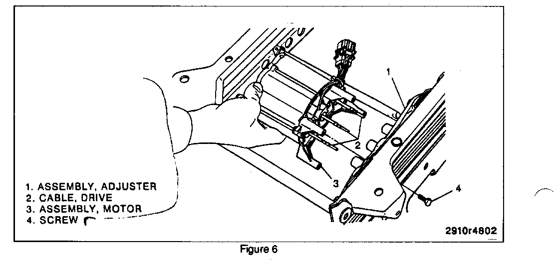
POWER SEAT MOTOR ASSEMBLY REPLACEMENT
Remove Or Disconnect: (Figure 6) -------------------------------- 1. Seat from the vehicle. Refer to "Seat Replacement".
2. Motor assembly to the adjuster screws.
3. Motor assembly from the adjuster.
Install Or Connect: (Figure 6) ------------------------------ 1. Motor assembly to the adjuster.
2. Motor assembly to the adjuster screws.
3. Seat assembly to the vehicle. Refer to "Seat Replacement".
DRIVE CABLE REPLACEMENT
Remove Or Disconnect: (Figure 6) -------------------------------- 1. Seat assembly from the vehicle. Refer to "Seat Replacement".
2. Motor assembly from the adjuster. Refer to "Power Seat Motor Assembly Replacement".
3. Drive cables from the transmission.
Install Or Connect: (Figure 6) ------------------------------ 1. Drive cables to the transmission.
2. Motor assembly to the adjuster. Refer to "Power Seat Motor Assembly Replacement".
3. Seat assembly to the vehicle. Refer to "Seat Replacement".
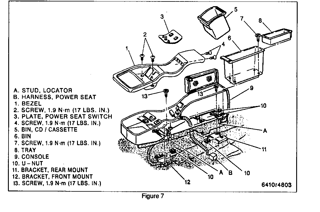
SEAT SWITCH REPLACEMENT
Remove Or Disconnect: (Figure 7) -------------------------------- 1. Negative battery cable. Refer to SECTION OA.
2. Large storage bin screws.
3. Large storage bin from the console.
4. CD/Cassette storage bin from the console.
5. Console trim bezel to the console screws.
6. Switch plate from the trim bezel.
A. Lift bezel upward to gain access to the snap fit clips retaining the switch plate.
B. Squeeze the retainer clips to release the switch plate from the bezel.
7. Electrical connections from the seat and lumbar switches.
Install Or Connect: (Figure 7) ------------------------------ Notice: For steps 3 and 6, refer to "Notice" on page 10A2-1 of the 1993 Bravada Service Manual.
1. Electrical connections to the switches.
2. Switch plate to the trim bezel.
3. Console trim bezel to the console screws.
Tighten
o Trim bezel to the console screws to 1.9 N.m (17 lbs. in.).
4. CD/Cassette storage bin to the console.
5. Large storage bin to the console.
6. Large storage bin to the console screws.
Tighten
o Storage bin to the console screws to 1.9 N-m (17 lbs. in.).
7. Negative battery cable. Refer to SECTION OA.
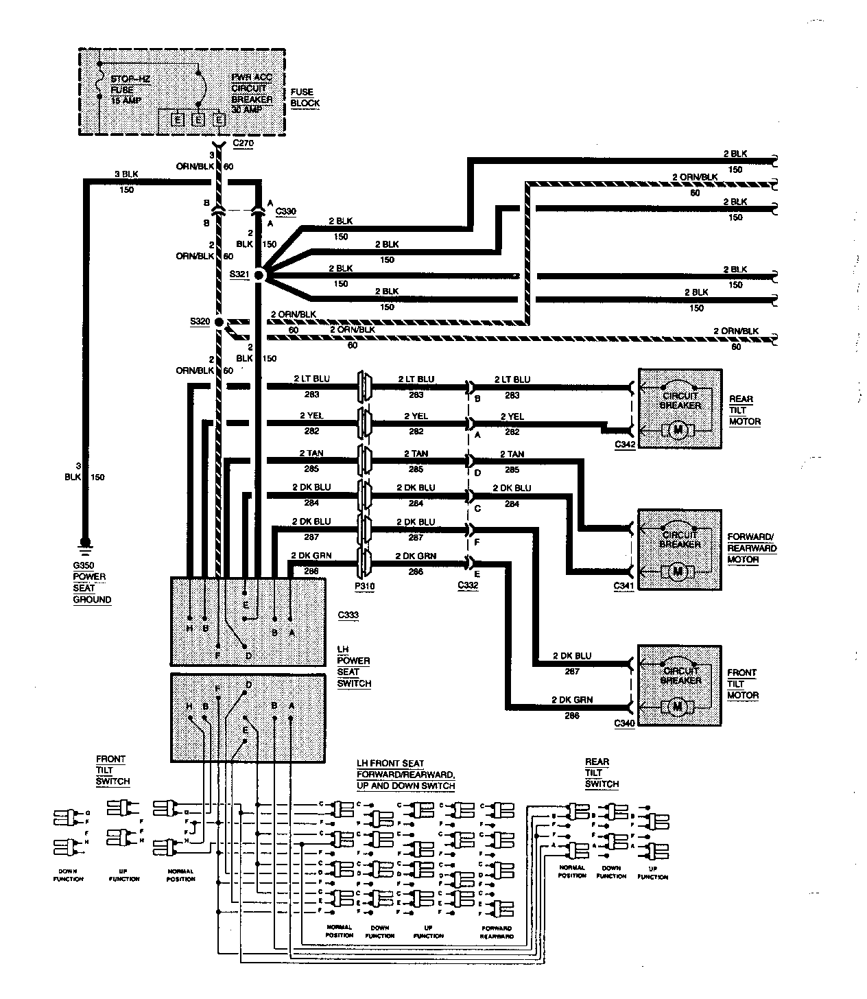
CIRCUIT OPERATION
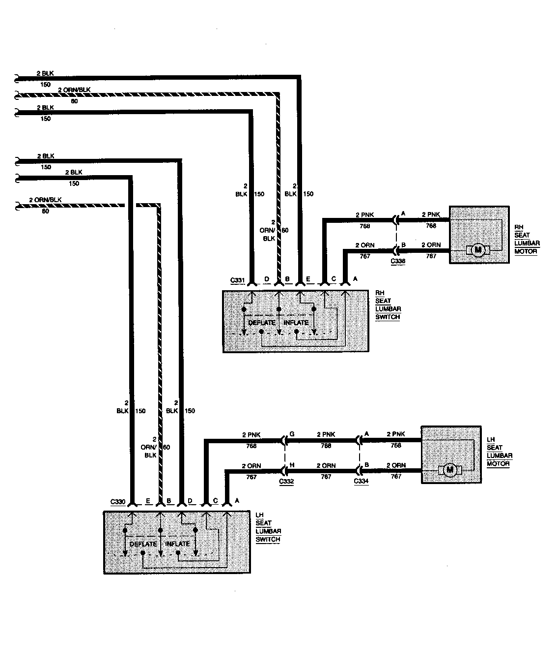
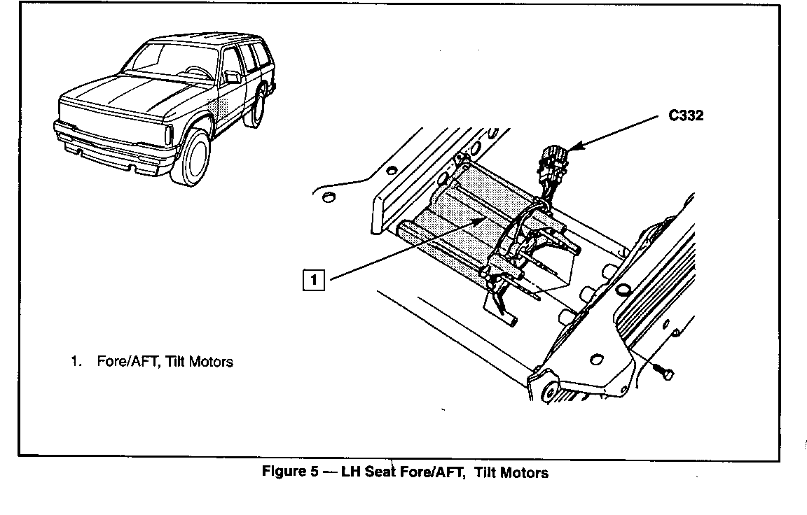
Three reversible motors operate the driver's power seat. One motor raises or lowers the front of the seat. One motor raises or lowers the rear of the seat. The third motor moves the seat forward or back.
Moving the Front Tilt Switch UP supplies voltage to the Front Tilt Motor through the LT BLU (283) wire. The motor is grounded through the Front Tilt Switch through the YEL (282) wire. Moving the Front Tilt Switch to the DOWN position reverses the polarity and the front of the seat is lowered.
The Rear Tilt Motor is operated in the same way through the Rear Tilt Switch.
Moving the Forward/Rearward, Up and Down Switch up or down operates the Front Tilt Motor and Rear Tilt Motor at the same time.
Moving the Forward/Rearward, Up and Down Switch up or down operates the Fore/Aft Motor and the seat moves forward or back.
A reversible motor located in the seat back inflates and deflates the Lumbar support in each seat.
Moving the Lumbar Switches to the INFLATE position supplies voltage to the Lumbar Motor through the PNK (768) wire. The motor is grounded through the Lumbar Switch and the ORN (767) wire. Moving the Lumbar Switch to the DEFLATE position reverses the polarity and causes the Lumbar support to return to its normal position.
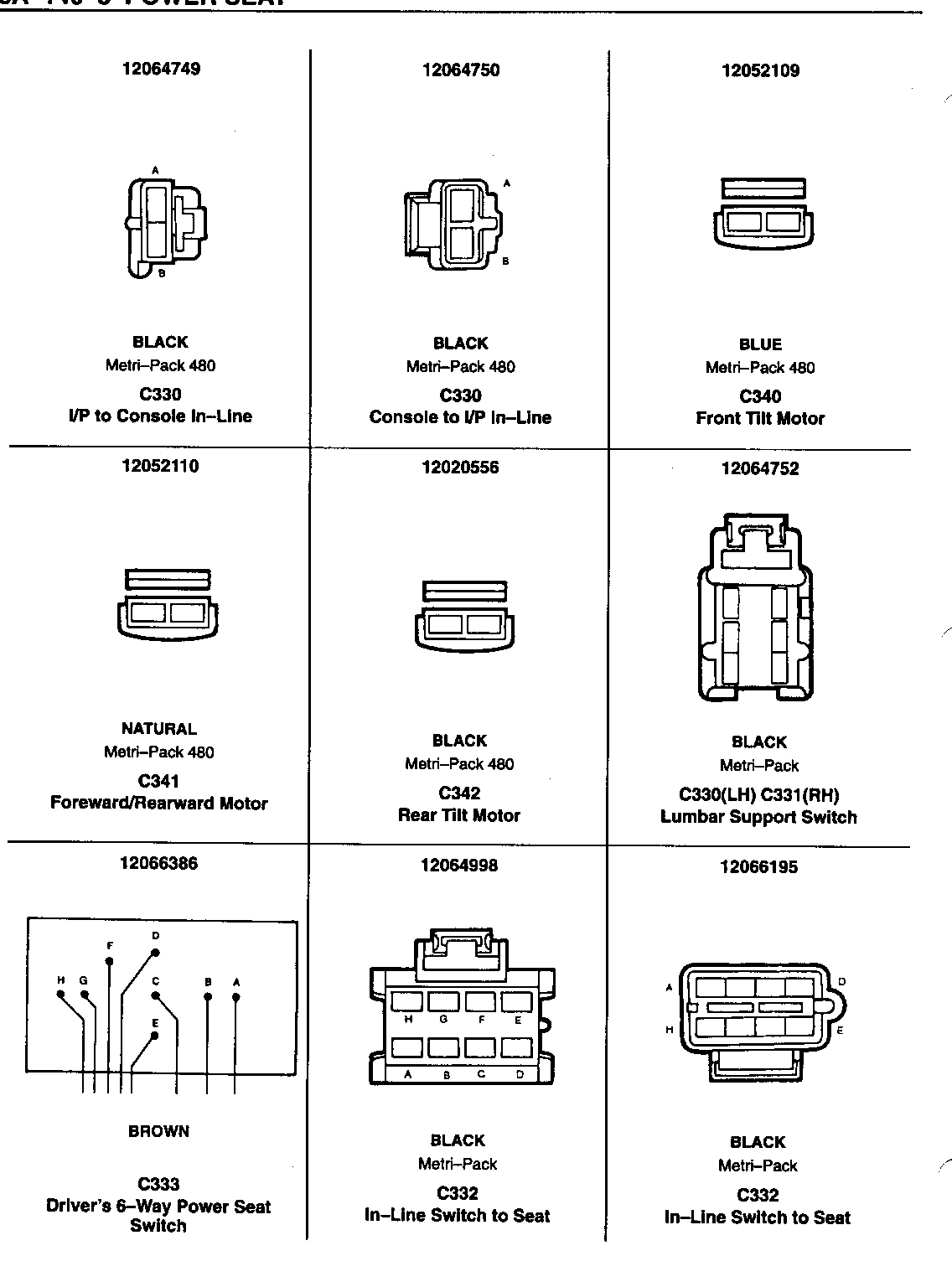
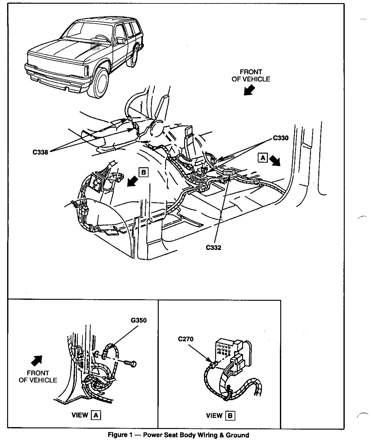
COMPONENT LOCATION Page-Figure ------------------ ----------- Fore/Aft Motor................... Below LH seat................. 8A-140-12-5 Front Tilt Motor................. Below LH seat................. 8A-140-12-5 Fuse Block....................... Behind LH side of I/P......... 8A-140-11-2 Lumbar Motor, LH................. In LH seat back............... 8A-140-12-4 Lumbar Motor, RH................. In RH seat back............... 8A-140-12-4 Lumbar Switch, LH................ Top front of center console... 8A-140-11-3 Lumbar Switch, RH................ Top front of center console... 8A-140-11-3 Power Seat Switch, LH............ Top front of center console... 8A-140-11-3 Rear Tilt Motor.................. Below LH seat................. 8A-140-12-5
CONNECTORS:
---------- C330........................ Below LH seat, near floor ......... 8A-140-10-1 C332........................ Below LH seat, near floor ......... 8A-140-10-1
GROUNDS:
------- G350........................ Lower LH B-pillar ................. 8A-14G-10-1
GROMMETS:
-------- P300........................ Bottom LH side of center console... 8A-140-11-3
SPLICES:
------- S320........................ Under center console .............. 8A-140-11-3 S321........................ Under center console .............. 8A-140-11-3
DIAGNOSIS - POWER SEAT
PRELIMINARY CHECKS:
1. Check to see that the PWR ACC circuit breaker is resetting. Replace if necessary.
2. Refer to Section 10A2 of this manual for diagnosis and repair of all non-electrical system components.
POWER SEAT DOES NOT OPERATE IN ANY DIRECTION
TEST RESULT ACTION ---- ------ ------ 1. Remove power seat switch Test lamp lights. GO to step 2. assembly from connector C333.
Connect test lamp from Test lamp does not LOCATE and REPAIR ORN/BLK (60) wire at light. open in ORN/BLK (60) connector C333 to wire from seat switch ground. connector C333 to splice S320 or from splice S320 to con- nector C330 or from connector C330 to fuse block.
2. Connect ohmmeter from BLK Continuity. Go to "Power Seat (150) wire at seat switch Does Not Tilt Forward" assembly connector C330 diagnosis. to ground. No continuity. LOCATE and REPAIR open in BLK (150) wire from seat switch assembly con- nector C333 to splice S321 or from splice S321 to connector C330 or from con- nector to ground G350.
POWER SEAT DOES NOT TILT FORWARD
TEST RESULT ACTION ---- ------ ------ 1. Using a jumper lead, Motor moves. REPLACE switch connect YEL (282) wire assembly. to BLK (150) wire cavity at seat switch assembly connector C333.
Connect jumper momentarily from LT BLU (283) wire to Motor does not move. GO to step 2. ORN/BLK (60) wire at seat switch assembly connector C333.
2. Connect LT BLU (283) wire to Motor moves. REPLACE power seat BLK (150) wire at power seat switch assembly. switch assembly connector C333 with a jumper lead.
Momentarily connect YEL (282) wire to ORN/BLK (60) Motor does not move. GO to step 3. wire with a jumper lead at seat switch connector C333.
3. Connect YEL (282) wire to Continuity. REPLACE rear tilt LT BLU (283) wire at power motor. seat switch assembly connector C333.
Remove connector C342 from No continuity LOCATE and REPAIR rear tilt motor. Using an open in YEL (282) ohmmeter check YEL (282) wire and/or LT BLU wire and LT BLU (283) wire (283) wire from rear for continuity to each tilt motor connector other. C342 to power seat switch assembly con- nector C333.
POWER SEAT DOES NOT TILT TO THE REAR
TEST RESULT ACTION ---- ------ ------ 1. Connect DK GRN (286) wire to Motor moves. REPLACE power seat BLK (150) wire at power seat switch assembly. switch assembly connector C333 with a jumper lead.
Momentarily connect DK BLU Motor does not move. GO to step 2. (287) wire to ORN/BLK (60) wire with a jumper lead.
2. Connect DK BLU (287) wire to Motor moves. REPLACE power seat BLK (150) wire at power seat switch assembly. switch assembly connector C333 with a jumper lead.
Momentarily connect DK GRN (286) wire to ORN/BLK Motor does not move. GO to step 3. (60) wire with a jumper lead.
3. Connect DK GRN (286) wire to Continuity. REPLACE rear tilt DK BLU (287) wire at power seat motor. switch assembly connector C333.
Remove connector C340 from No continuity. LOCATE and REPAIR front tilt motor. Using an open in DK GRN (286) ohmmeter check DK GRN (286) wire and/or DK BLU wire and DK BLU (287) wire (287) wire from front for continuity to each other. tilt motor connector C340 to power seat switch assembly con- nector C333.
POWER SEAT DOES NOT MOVE FORWARD/REARWARD ----------------------------------------- TEST RESULT ACTION ---- ------ ------ 1. Connect LT GRN (284) wire to Motor moves. REPLACE power seat BLK (150) wire at power seat switch assembly. switch assembly connector C333 with a jumper lead.
Momentarily connect TAN (285) Motor does not move. GO to step 2. wire to ORN/BLK wire with a jumper lead.
2. Connect TAN (285) wire to BLK Motor moves. REPLACE power seat (150) wire cavity at power seat switch assembly. switch assembly connector C333 with a jumper lead.
Momentarily connect LT GRN Motor does not move. GO to step 3. (284) wire to ORN/BLK (60) wire with a jumper lead.
3. Connect TAN (285) wire to Continuity. REPLACE forward/rear- LT GRN (284) wire at power ward motor. seat switch assembly connector C333.
Remove connector C341 from No continuity LOCATE and REPAIR forward/rearward motor. Using open in TAN (285) an ohmmeter check TAN (285) wire and/or LT GRN wire and LT GRN (284) wire (284) wire from for- for continuity to each other. ward/rearward motor connector C341 to power seat switch assembly connector C333.
LH SEAT LUMBAR DOES NOT OPERATE (FORE/AFT, UP/DOWN AND TILT OPERATE PROPERLY) ----------------------------------------------------------------------------- TEST RESULT ACTION ---- ------ ------ 1. Connect test lamp from Test lamp lights. GO to step 2. ORN/BLK (60) wire at Lumbar Switch connector Test lamp does not LOCATE and REPAIR C330. light. open in ORN/BLK (60) wire between Lumbar Switch con- nector C330 and splice S320.
2. Connect test lamp from Test lamp lights. GO to step 3. ORN/BLK (60) wire to BLK (150) wires at Lumbar Test lamp does not LOCATE and REPAIR Switch connector C330. light. open in BLK (150) wires between Lumbar Switch connector and splice S321.
3. Disconnect Lumbar Switch Motor operates. Replace Lumbar Switch connector C330. Connect PNK (768) wire to BLK (150) wire pin D at Lumbar Switch connector C330.
Momentarily connect ORN Motor does not GO to step 4. (767) wire to ORN/BLK operate. ORN/BLK(60) wire with a jumper lead.
4. Connect ORN (767) wire to Motor operates. REPLACE Lumbar BLK (150) wire pin E at Lumbar Switch. Switch connector C330.
Momentarily connect PNK (768) Motor does not GO to step 5. wire to ORN/BLK (60) wire operate. with a jumper lead.
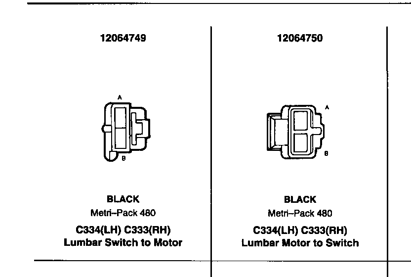
5. Connect ORN (767) wire to Continuity. REPLACE Lumbar Motor. PNK (768) wire at Lumbar Switch connector C330. Disconnect No continuity. LOCATE and REPAIR connector C334 from Lumbar open in ORN (767) Motor. Using an ohmmeter, check and/or PNK (768) ORN (767) and PNK (768) wires wires from Lumbar for continuity to each other. Switch connector C330 to in-line seat connector C332 or from in-line seat connector C332 to Lumbar Motor connector C334.
RH SEAT LUMBAR DOES NOT OPERATE (LH SEAT LUMBAR OPERATES PROPERLY)
TEST RESULT ACTION ---- ------ ------ 1. Connect test lamp from ORN/ Test lamp lights. GO to step 2. BLK (60) wire at Lumbar Switch connector C331 to Test lamp does not LOCATE and REPAIR ground. light. open in ORN/BLK (60) wire between Lumbar Switch connector C331 and splice S320.
2. Connect test lamp from ORN/ Test lamp lights. GO to step 3. BLK (60) wire to BLK (150) wires at Lumbar Switch Test lamp does not LOCATE and REPAIR connector C331. light. open in one or both BLK (150) wires between Lumbar Switch connector C331 and splice S321.
3. Disconnect Lumbar Switch Motor operates. REPLACE Lumbar Switch connector C331. Connect PNK (768) wire to BLK (150) wire pin D at Lumbar Switch connector C331.
Momentarily connect ORN Motor does not GO to step 4. (767) wire to ORN/BLK operate. (60) wire with a jumper lead.
4. Connect ORN (767) wire to Motor operates. REPLACE Lumbar Switch BLK (150) wire pin E at Lumbar Switch connector C331.
Momentarily connect PNK Motor does not GO to step 5. (768) wire to ORN/BLK operate. (60) wire using a jumper lead.
5. Connect ORN (767) wire to Continuity REPLACE Lumbar Motor. PNK (768) wire at Lumbar Switch connector C331.
Disconnect Lumbar Motor No continuity LOCATE and REPAIR connector C338. Using an open in ORN (767) and ohmmeter, check ORN (767) /or PNK (768) wires and PNK (768) wires for between Lumbar Motor continuity to each other. connector C338 and Lumbar Switch con- nector C331.
General Motors bulletins are intended for use by professional technicians, not a "do-it-yourselfer". They are written to inform those technicians of conditions that may occur on some vehicles, or to provide information that could assist in the proper service of a vehicle. Properly trained technicians have the equipment, tools, safety instructions and know-how to do a job properly and safely. If a condition is described, do not assume that the bulletin applies to your vehicle, or that your vehicle will have that condition. See a General Motors dealer servicing your brand of General Motors vehicle for information on whether your vehicle may benefit from the information.
