SERVICE MANUAL UPDATE - SEC. 7 TRANS. UNIT REPAIR INFORMATION

SUBJECT: TRANSMISSION UNIT REPAIR INFORMATION
MODEL/YEARS: 1993 BRAVADA WITH THE 4L60-E TRANSMISSION
BULLETIN COVERS: New Product Information for 1993 HYDRA-MATIC 4L60-E transmissions. This information has been updated since publication of the 1993 Service Manual and should be noted accordingly. Be certain to familiarize yourself with these updates to properly repair the 1993 HYDRA-MATIC 4L60-E transmission.
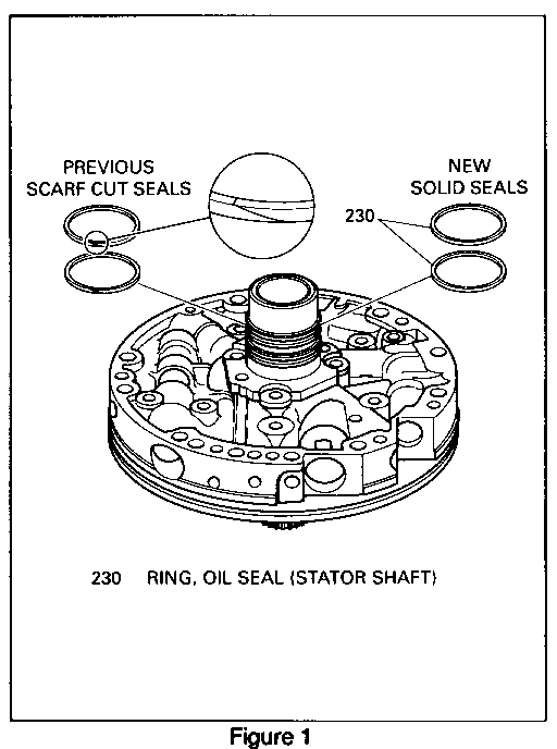
DATE OF PRODUCTION CHANGE: (Figure 1 and 2) ------------------------------------------- Beginning with Start of Production 1993, HYDRA-MATIC 4L60-E transmissions were built with solid stator shaft seals (230).
Note: The solid stator shaft seals should be used on past model 4L60 transmissions.
SERVICE MANUAL REFERENCE:
Update your 1993 Service Manual with the following three (3) pages.
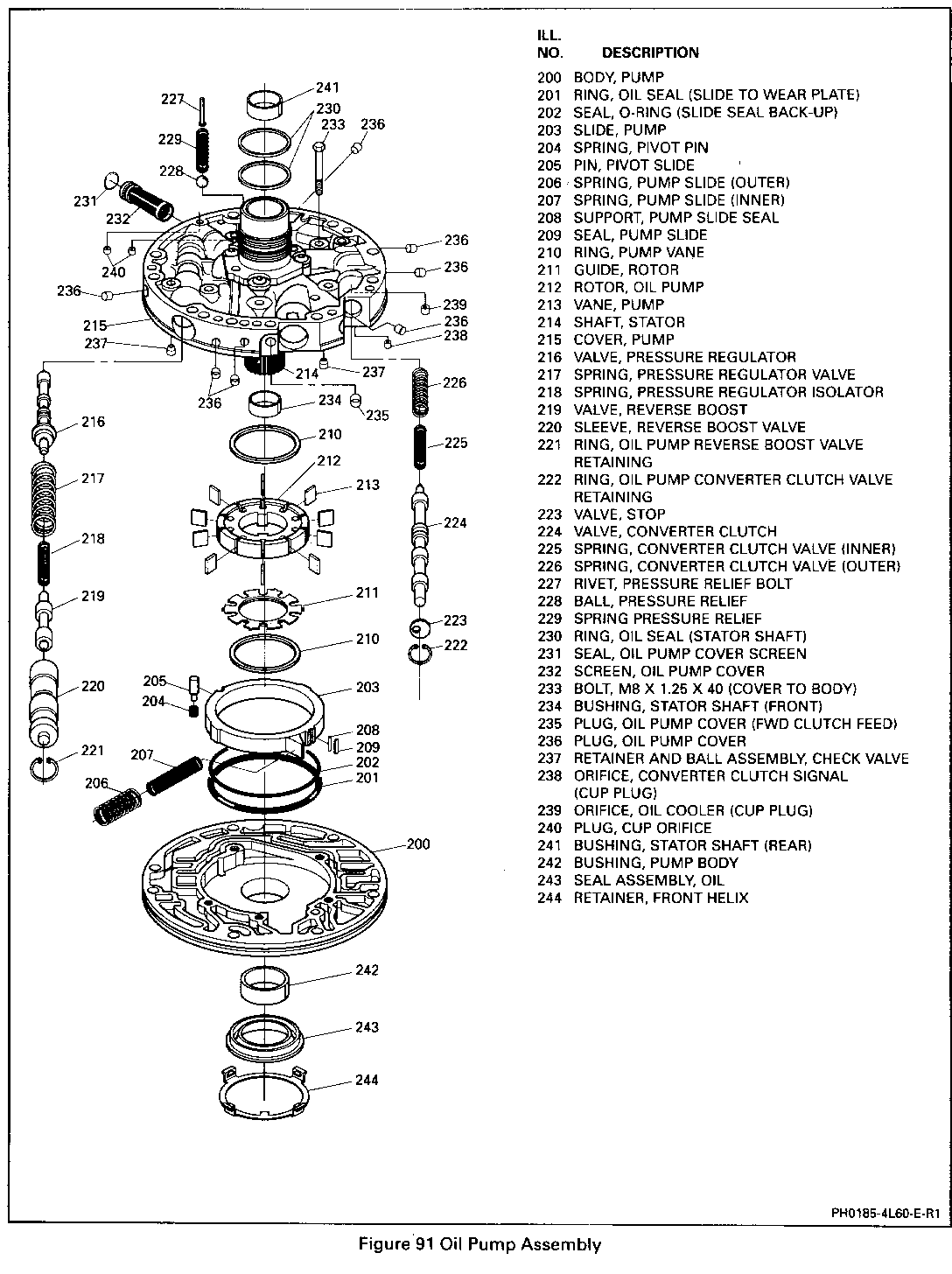
**PLEASE REFER TO FIGURE 91 OIL PUMP ASSEMBLY** ----------------------------------------------- ILL. NO. DESCRIPTION ---- ----------- 200 BODY, PUMP 201 RING, OIL SEAL (SLIDE TO WEAR PLATE) 202 SEAL, 0-RING (SLIDE SEAL BACK-UP) 203 SLIDE, PUMP 204 SPRING, PIVOT PIN 205 PIN, PIVOT SLIDE 206. SPRING, PUMP SLIDE (OUTER) 207 SPRING, PUMP SLIDE (INNER) 208 SUPPORT, PUMP SLIDE SEAL 209 SEAL, PUMP SLIDE 210 RING, PUMP VANE 211 GUIDE, ROTOR 212 ROTOR, OIL PUMP 213 VANE, PUMP 214 SHAFT, STATOR 215 COVER, PUMP 216 VALVE, PRESSURE REGULATOR 217 SPRING, PRESSURE REGULATOR VALVE 218 SPRING, PRESSURE REGULATOR ISOLATOR 219 VALVE, REVERSE BOOST 220 SLEEVE, REVERSE BOOST VALVE 221 RING, OIL PUMP REVERSE BOOST VALVE RETAINING 222 RING, OIL PUMP CONVERTER CLUTCH VALVE RETAINING 223 VALVE, STOP 224 VALVE, CONVERTER CLUTCH 225 SPRING, CONVERTER CLUTCH VALVE (INNER) 226 SPRING, CONVERTER CLUTCH VALVE (OUTER) 227 RIVET, PRESSURE RELIEF BOLT 228 BALL, PRESSURE RELIEF 229 SPRING PRESSURE RELIEF 230 RING, OIL SEAL (STATOR SHAFT) 231 SEAL, OIL PUMP COVER SCREEN 232 SCREEN, OIL PUMP COVER 233 BOLT, M8 X 1.25 X 40 (COVER TO BODY) 234 BUSHING, STATOR SHAFT (FRONT) 235 PLUG, OIL PUMP COVER (FWD CLUTCH FEED) 236 PLUG, OIL PUMP COVER 237 RETAINER AND BALL ASSEMBLY, CHECK VALVE 238 ORIFICE, CONVERTER CLUTCH SIGNAL (CUP PLUG) 239 ORIFICE, OIL COOLER (CUP PLUG) 240 PLUG, CUP ORIFICE 241 BUSHING, STATOR SHAFT (REAR) 242 BUSHING, PUMP BODY 243 SEAL ASSEMBLY, OIL 244 RETAINER, FRONT HELIX
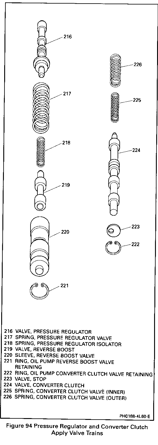
8. Reverse boost valve (219) into the reverse boost valve sleeve.
o Small end of the valve first
o Retain with Transjel TM J 36850 or equivalent.
9. Reverse boost valve sleeve (220) into the pressure regulator bore.
10. Retainer ring (221).
Oil Pump Cover and Body
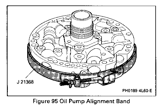
Figures 91 and 95 through 98
Tools Required:
J 21368 Oil Pump Body and Cover
Alignment Band
J 25025-1 Alignment Pins
Assemble
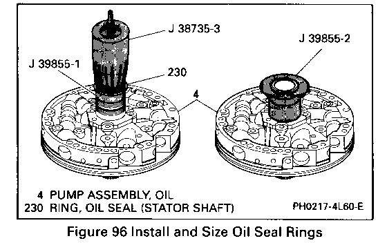
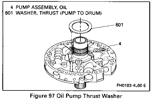
Figures 91, 95, 96 and 97
1. Oil pump cover (215) onto oil pump body.
o Stator shaft through a bench hole
2. Pump cover bolts (233).
o Leave finger tight.
3. Align pump cover and pump body with J 21368.
o Place a screwdriver through a bolt hole and into a hole in the bench.
Tighten
o Attaching bolts to 24 N-m (18 lb. ft.).
o Retain with Transjel TM J 36850 or equivalent.
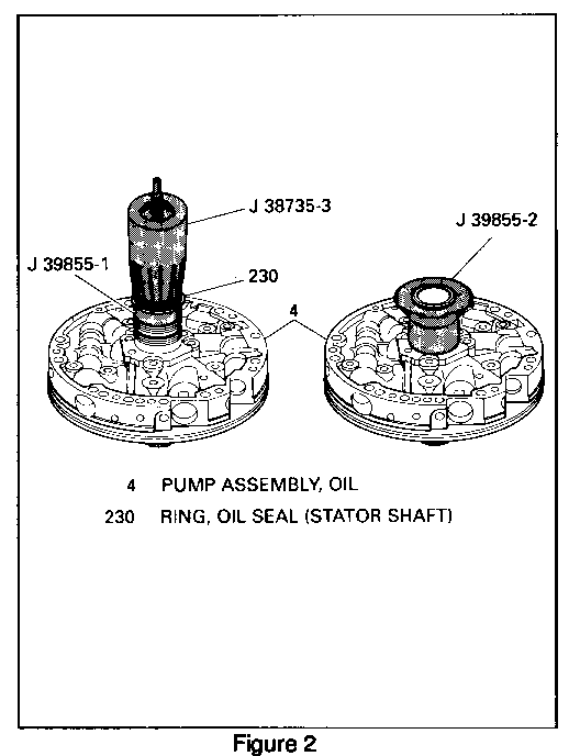
4. Install two oil seal rings (233) using J38735-3 and J 39855-1.
Adjust
o Adjust screw to obtain proper height.
5. Use J 39855-2 to size seals after installation.
Install or Connect
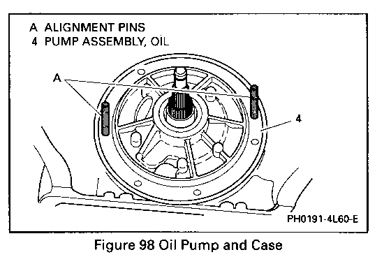
Figure 98
1. Thrust washer (601).
2. J 25025-1 into the case as shown.
3. Oil pump assembly into the case.
o Align all holes properly.
4. Bolts and 0-rings (2 and 3).
Tighten
o Bolts to 24 N-m (18 lb. ft.).
Important
o Rotate the transmission to a horizontal position. If the transmission is assembled properly the turbine shaft should turn by hand. If not identify and correct the misassembly now.
Transmission End Play Check
Figures 99 through 103 and 106, 107 and 108
Tools Required:
J 24773-A End Play Checking Fixture
J 25022 End Play Checking Fixture Adaptor (245 mm)
J 34725 End Play Checking Fixture Adaptor (298 mm)
J 25025-7A Post or 278 mm (11 inch) Bolt and Nut
Dial indicator
Measure
Figures 99 through 102
1. Remove an oil pump to case bolt and install a 278 mm (11 inch) bolt and lock nut or J 25025- 7A.
2. Install J 25022-A or J 34725 as shown.
3. Install J 24773-A as shown.
4. Install a dial indicator.
o Set to zero.
5. Pull up on J 24773-A.
o End play should be 0. 13 to 0.92 mm (0.005 to 0.036 inch).
The selective washer which controls end play is located between the input housing and the thrust bearing on the oil pump hub. If more or less end play is required, select the proper washer from the chart and install. If dial indicator shows no end play, the selective washer and thrust bearing have been misassembled.
General Motors bulletins are intended for use by professional technicians, not a "do-it-yourselfer". They are written to inform those technicians of conditions that may occur on some vehicles, or to provide information that could assist in the proper service of a vehicle. Properly trained technicians have the equipment, tools, safety instructions and know-how to do a job properly and safely. If a condition is described, do not assume that the bulletin applies to your vehicle, or that your vehicle will have that condition. See a General Motors dealer servicing your brand of General Motors vehicle for information on whether your vehicle may benefit from the information.
