Transfer Case Motor/Encoder Replacement TrailBlazer, Envoy, Rainier, Bravada
Removal Procedure
Important: Before the motor/encoder is removed, ensure that the motor/encoder is in the 2HI position.
- Raise the vehicle. Refer to Lifting and Jacking the Vehicle in General Information.
- Remove the fuel tank shield, if equipped. Refer to Fuel Tank Shield Replacement in Frame and Underbody.
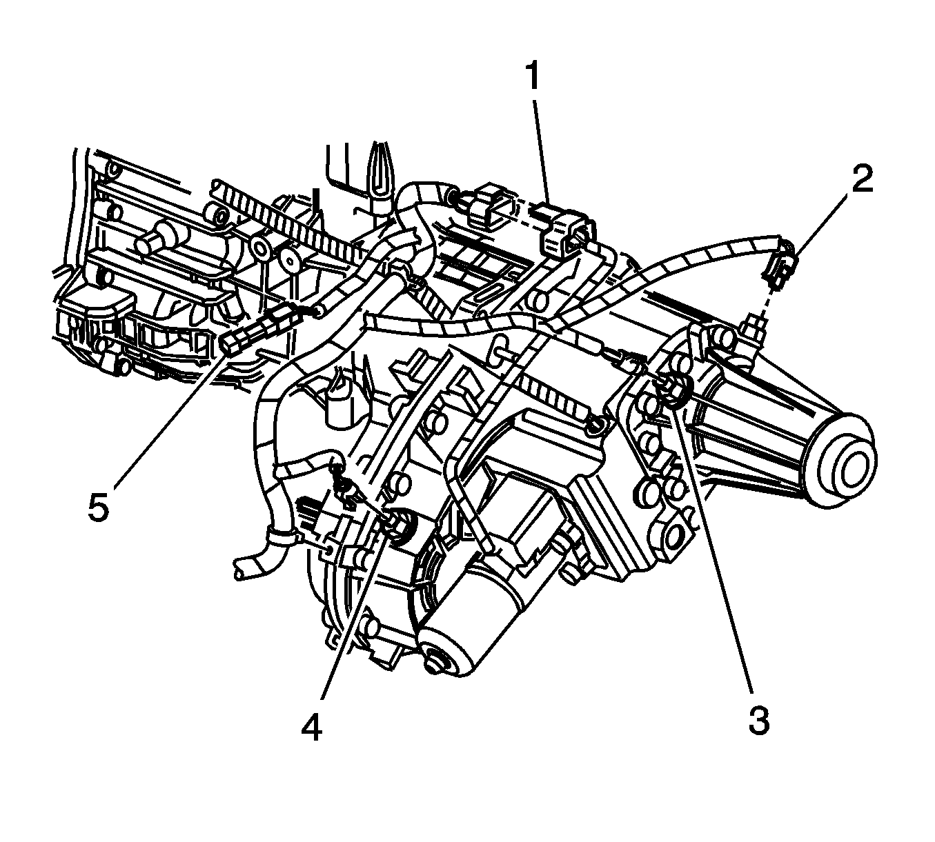
- Disconnect the motor/encoder electrical connector (1).
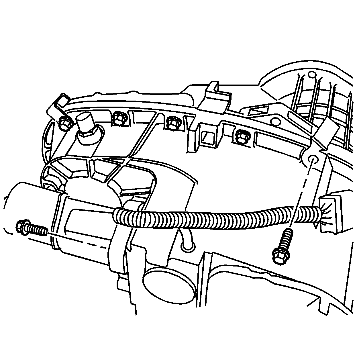
- Remove the motor/encoder mounting bolts.
- Remove the motor/encoder assembly.
- Position the motor on a work bench.
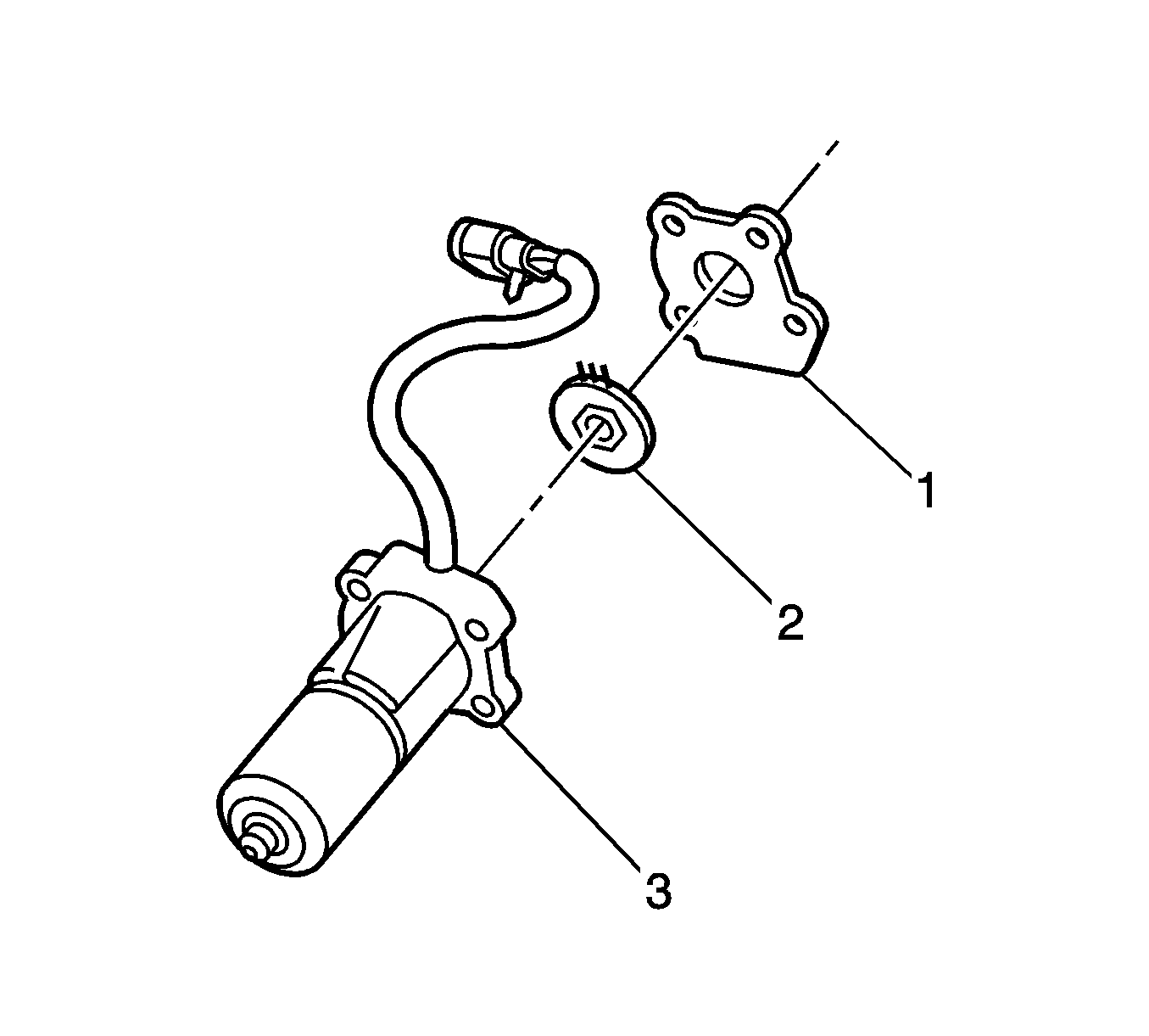
- Release the 4 tabs that retain the motor/encoder gasket and remove the gasket (1).
- Remove the snap ring and washer retaining the motor/encoder rotary position sensor.
- lift the motor/encoder rotary position sensor (2) from the motor shaft.
- Disconnect the rotary position sensor (2) from the wiring harness.
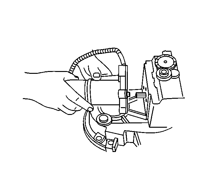
Important: When replacing the encoder rotary position sensor follow these additional steps. The rotary position sensor is circular with 3 contacts on one side and is positioned behind the motor/encoder gasket.
Important: Gently lift the rotary position sensor and wiring to disconnect it. The internal wires go to a connector within the motor housing. This internal wire connector does not have a locking tab and is easily disturbed.
Important: Look at the motor/encoder housing (1) where the rotary position sensor was removed from. Take note of the "Hex" in the housing where the new sensor will seat when properly installed.
Installation Procedure
- Connect the wiring harness to the rotary position sensor.
- Gently insert a suitable tool along side the internal wires and press down on the internal wire connector to insure the connector is fully installed.
- Properly align the keyway of the rotary position sensor with the motor/encoder shaft as indicated by the center reference line shown in the graphic.
- Ensure that the hex on the rotary position sensor (2) fits in the hex of the motor/encoder housing (3).
- Install the washer and snap ring retaining the motor/encoder rotary position sensor.
- Install the motor/encoder gasket (1).
- Install the motor/encoder to the transfer case.
- Install motor/encoder mounting bolts to the transfer case.
- Connect the motor/encoder electrical connector (1).
- Install the fuel tank shield, if equipped. Refer to Fuel Tank Shield Replacement in Frame and Underbody.
- Lower the vehicle. Refer to Lifting and Jacking the Vehicle in General Information.
Important: Provided the rotary position sensor was removed, follow steps to install the sensor, otherwise proceed to installing the motor/encoder to the transfer case.
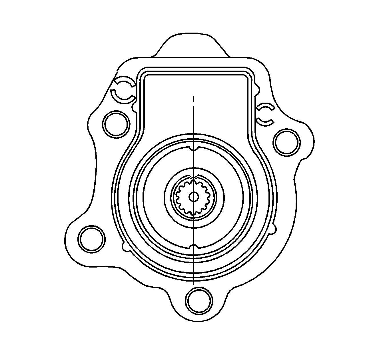


Important: When performing this service procedure, make sure that the motor/encoder unit is flat against the transfer case for proper installation.
Notice: Refer to Fastener Notice in the Preface section.

Tighten
Tighten the bolts to 16 N·m (12 lb ft).

