CAMPAIGN: POWERMASTER BRAKE SYSTEM DIAGNOSTIC PROCEDURE

Subject: POWERMASTER BRAKE SYSTEM
Models/Years: 1986 OLDSMOBILE CUSTOM CRUISER STATION WAGON
CONDITION
General Motors has determined that certain 1986 Oldsmobile Custom Cruiser Station Wagons with Powermaster brake systems were built with combination valves and pressure switches which may become faulty. If left uncorrected, these vehicles may experience a "hard brake pedal" or "increased brake pedal travel". These conditions may be caused by a cast iron combination valve allowing air to enter the brake system or by a pressure switch on the Powermaster Brake Assembly leaking brake fluid.
To prevent either of the above conditions from occurring, vehicles will be inspected and those equipped with the CAST IRON combination valve will receive a new BRASS combination valve. Also, the pressure switch will be inspected and replaced if necessary.
VEHICLES INVOLVED
Involved are certain 1986 Oldsmobile Custom Cruiser Station Wagons with Powermaster brake systems built from Start-of-production (S.O.P.) through the End-of-production (E.O.P.), within the following VIN breakpoints:
Through and Year Model Model Name Beginning Including ---- --------- -------------- --------- ---------- 1986 "B" Wagon Custom Cruiser G9000002 G9021070
DEALER ACTION
Dealers are to service all vehicles involved in this campaign, at no charge to owners, regardless of mileage, age of vehicle, or ownership.
Whenever a vehicle subject to this campaign is taken into your used vehicle inventory, or it is in your dealership for service, you are to ensure the campaign correction has been made before selling or releasing the vehicle.
Dealers are to contact owners of vehicles recently sold from your used vehicle inventory and arrange for the campaign correction to be performed.
SERVICE PROCEDURE
1. Open hood and inspect pressure switch. If the current pressure switch terminal body is GRAY, move on to Step (2). If the current switch terminal body is BLACK, place a fender cover on the left fender, then remove and replace the pressure switch according to the procedure below. After that, move on to Step 2.
A. Depressurize the Powermaster unit by turning ignition "OFF", then apply and release brake pedal a minimum of ten (10) times using approximately fifty (50) pounds of force on pedal to fully deplete the power assist.
CAUTION:
Failure to fully depressurize the Powermaster unit could result in brake fluid being sprayed on service personnel and could cause damage to painted surfaces.
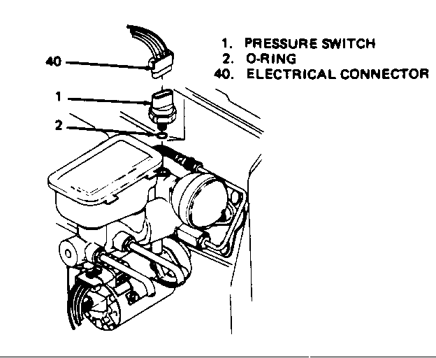
B. Disconnect the 3-wire electrical connector (Figure 1, 40) from the pressure switch (Figure 1, 1).
C. Remove the old pressure switch (Figure 1, 1). The original O-ring should be on the old pressure switch. If not, check Powermaster unit for the loose 0-ring and remove it. Take care not to drip brake fluid on painted surfaces.
The old pressure switch has only one O-ring. Do NOT reuse the old O-ring.
D. Obtain new Pressure Switch (P/N 18018141). The new pressure switch has an 0-ring already installed in a groove on it. A second 0-ring should be found loose in the box with the switch. Lubricate the second 0-ring (Figure 1, 2) with clean, fresh brake fluid (DOT #3) and install in a groove between the threads and the existing 0-ring on the new pressure switch.
E. Install new Pressure Switch (Figure 1, 1) and torque to 24 N.m (18 lbs.-ft.)
NOTE: Torque values specified are for dry, unlubricated fasteners.
F. Reconnect 3-wire electrical connector (Figure 1, 40) to Pressure Switch (Figure 1, 1). Be sure electrical connector is securely seated.
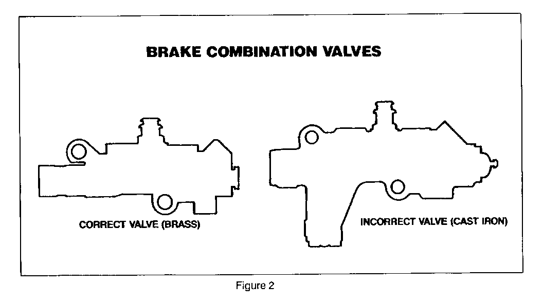
2. Locate combination valve (on frame rail below master cylinder). If the current combination valve is Cast Iron, the valve must be replaced with a Brass valve by following the procedure below. If the vehicle already has the Brass valve, the combination valve does NOT need to be replaced; proceed to Step 3. Figure 2 illustrates the differences in the two valves.
A. Remove the electrical wiring harness connector from the pressure differential switch by squeezing the eliptical-shaped plastic lock ring and pulling up. A pair of pliers may aid in removing the connector.
B. Disconnect hydraulic lines at combination valve. Plug lines to prevent loss of fluid and entrance of dirt.
C. Remove Cast Iron Combination Valve.
D. Install Brass Combination Valve. Torque mounting bolts to 20 N.m (1 4 lbs.-ft.).
E. Remove plugs and connect hydraulic lines at Combination Valve. Torque hydraulic fittings to 24 N. m (18 lbs. -ft.).
F. Connect electrical wiring harness connector to pressure control differential switch.
G. Bleed entire brake system following the procedure in section 5D4 of the 1986 Oldsmobile Cutlass Supreme, Cutlass Saloon, Custom Cruiser Chassis Service Manual. Do not move vehicle until a firm brake pedal is obtained.
H. Check brake lines for proper clearance.
3. Install Campaign Identification Label.
CAMPAIGN IDENTIFICATION LABEL
Each label provides space to print the campaign number, and the five (5) digit dealer code of the dealer performing the campaign. Insert this information with a typewriter or ballpoint pen. When installing label, clean and dry the surface of the radiator support tie bar and apply the campaign label where it is readily visible.
PARTS INFORMATION
To ensure parts are obtained as soon as possible, order them from GM Service Parts Operations (GMSPO) on a C.I.O. order, with NO special instruction code, but order on an advise code (2). Use the following part numbers:
Description Part Number Quantity Per Vehicle ----------------------- ----------- -------------------- Brass Combination Valve 25509419 1
Pressure Switch (Includes 18018141 1 2 0-rings, one loose, and one on the Pressure Switch)
OWNER REIMBURSEMENT
Customers may request reimbursement for prior replacement of the Powermaster Brake Assembly, combination valve, and/or pressure switch. Owners must submit original documentation that reasonably confirms the amount of unreimbursed repair expenses, a description of the repair, the date of the repair, and the person or entity performing the repair to receive reimbursement.
Claims for customer reimbursement on previously paid repairs are to be submitted according to the Warranty Claim Information instructions. Use the "Owner Reimbursement" labor operation and list all owner expenses concerning previous repairs in the net items column of the warranty claim. PRIOR ZONE AUTHORIZATION REQUIRED.
NOTE: When a customer requests reimbursement, and the vehicle is still available, dealers are to inspect and install the new pressure switch and/or combination valve, if necessary, as called for in the SERVICE PROCEDURE of this bulletin. Until the involved vehicle is inspected and/or repaired, the campaign will remain open.
WARRANTY CLAIM INFORMATION
Submit claims using no more than one of the "V" labor-ops below for each vehicle. As appropriate, both a "T" labor- op and one "V" labor-op may be submitted on a vehicle.
REPAIR PERFORMED TOT-PTS FC LAB-OP LHRS --------------------- ------- -- ----- ---- Inspect Pressure Switch 96 V6160 0.2* or Combination Valve - No Replacements Needed
Inspect Combo Valve & 96 V6161 0.4* Pressure Switch - Replace Pressure Switch Only
Inspect Combo Valve & 96 V6162 0.9* Pressure Switch - Replace Combo Valve Only
Inspect/Replace 96 V6163 1.2* Combo Valve and Pressure Switch
Owner Reimbursement For -- 96 T1640 --- Prior Replacement Of The Powermaster Brake Assembly, Combination Valve, And/Or Pressure Switch (Prior Zone authorization required)
* .1 hour for clerical administration may be added to the published labor hours.
Parts allowance: Current dealer price, plus 30% handling allowance.
The cost of brake fluid may be applied for in the usual manner.


General Motors bulletins are intended for use by professional technicians, not a "do-it-yourselfer". They are written to inform those technicians of conditions that may occur on some vehicles, or to provide information that could assist in the proper service of a vehicle. Properly trained technicians have the equipment, tools, safety instructions and know-how to do a job properly and safely. If a condition is described, do not assume that the bulletin applies to your vehicle, or that your vehicle will have that condition. See a General Motors dealer servicing your brand of General Motors vehicle for information on whether your vehicle may benefit from the information.
