MIXTURE CONTROL ADJUST NEW SPECIFICATIONS

An important change has been made in the procedure for adjusting the Lean Mixture Screw and the Idle Air Bleed Valve on Computer Command Controlled Quadrajet and Dualjet carburetors. The new procedure involves making a setting to a dimension, rather than by making a specific number of adjustment screw turns. It is possible to adjust a carburetor following overhaul, or to readjust a carburetor when a System Performance check indicates this is required.
The new procedure applies to all "Closed Loop" Dualjets and Quadrajets (E2MC, E2ME, E4MC and E4ME) manufactured, starting with 1978 California models. Revised specifications for these adjustments are also included.
MIXTURE CONTROL SOLENOID PLUNGER ADJUSTMENTS
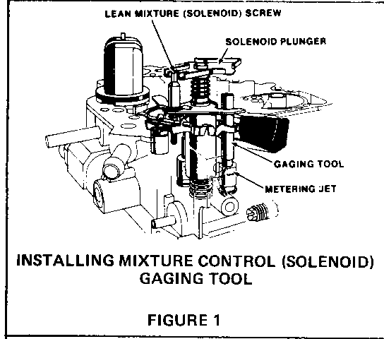
Refer to Figure 1 - Installing Mixture Control (Solenoid) Gaging Tool
1. Remove air horn, mixture control solenoid plunger, air horn gasket and plastic filler block, using normal service procedures.
2. Remove throttle side metering rod. Install mixture control solenoid gaging tool, J33815-1, BT-8253-A, or equivalent, over the throttle side metering jet rod guide. Reinstall solenoid plunger.
ADJUSTING LEAN MIXTURE (SOLENOID) SCREW
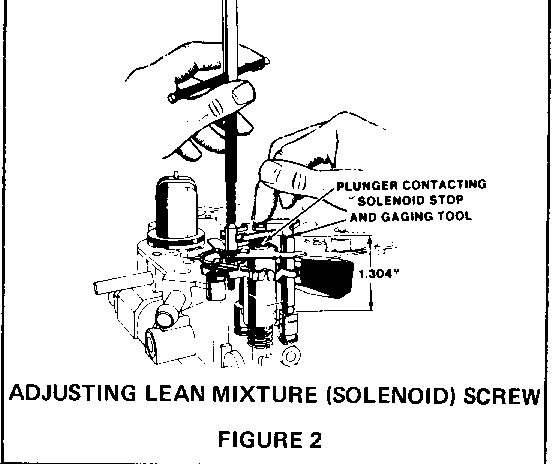
Refer to Figure 2- Adjusting Lean Mixture (Solenoid) Screw
3. Hold the solenoid plunger down, against the solenoid stop or gaging tool, and use tool J-28696-10, BT-7928, or equivalent, to turn lean mixture screw counterclockwise until the plunger breaks contact with the gaging tool. Turn slowly clockwise until the plunger just contacts the gaging tool. The adjustment is correct when the solenoid plunger contacts BOTH the SOLENOID STOP and the GAGING TOOL.
If the difference in adjustment of the lean mixture (solenoid) screw was less than 3/4 turn, the original setting had been made within specifications.
4. Remove gaging tool, and reassemble float bowl.
5. Remove lean mixture screw plug and rich mixture stop screw plug from the air horn, and reassemble carburetor.
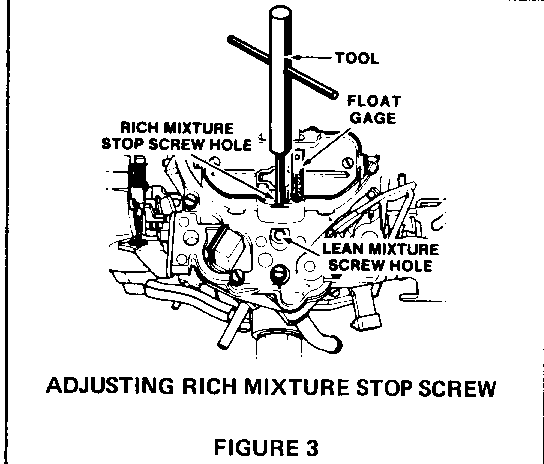
6. Insert external float gage, J-9789-130, BT-7720, or equivalent, in vent hole. Use tool J-28696-10, BT-7928, or equivalent, to adjust rich mixture stop screw to obtain 4/32 inch total plunger travel.
Refer to Figure 3 - Adjusting Rich Mixture Stop Screw
7. Install new screw plugs, supplied in service kit.
IDLE MIXTURE ADJUSTMENTS
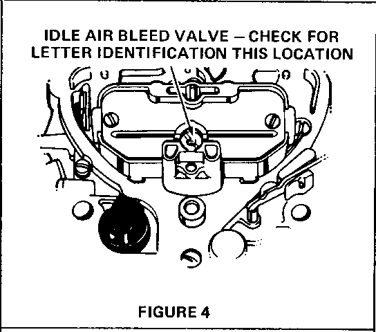
Refer to Figure 4 - Idle Air Bleed Valve - - Check for Letter Identification
With cover removed from the Idle Air Bleed Valve, look for the presence (or absence) of an identifying letter on the top face of the valve:
If there is NO letter, begin PROCEDURE A, (below). If there IS a letter, begin PROCEDURE B.
PROCEDURE A (No Letter on Idle Air Bleed Valve)
Carburetor WITHOUT letter identification on the idle air bleed valve is adjusted by:
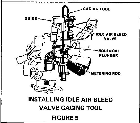
Refer to Figure 5 - Installing Idle Air Bleed Valve Gaging Tool
1. PRESETTING THE IDLE AIR BLEED VALVE (Only necessary if idle air bleed valve was serviced prior to on vehicle adjustment.):
a. Install idle air bleed valve gaging tool J-33815-2, BT-8253-B, or equivalent, in throttle side "D" shaped vent hole in the air horn casting. The upper end of the tool should be positioned over the open cavity next to the idle air bleed valve.
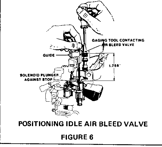
Refer to Figure 6 - Positioning Idle Air Bleed Valve
b. Hold the gaging tool down lightly, so that the solenoid plunger is against the solenoid stop, and adjust the idle air bleed valve so that the gaging tool will pivot over and just contact the top of the valve. The valve is now preset for on-vehicle adjustment.
c. Remove gaging tool.
2. ADJUSTING THE IDLE AIR BLEED VALVE
a. BLOCK DRIVE WHEELS. Place transmission in PARK (automatic transmission) or NEUTRAL (manual transmission), and set parking brake. Start engine and allow it to reach normal operating temperature.
b. While idling in DRIVE (NEUTRAL for manual transmission), slowly turn valve clockwise or counterclockwise, until the dwell reading varies within the 25-35 DEG range, attempting to be as close to 30 DEG as possible. The air bleed valve is very sensitive, and should only be turned 1/8 turn at a time.
c. If the dwell reading does not vary and is not within the 25-35 DEG range, it is necessary to remove the plugs and to adjust the idle mixture needles.
3. SETTING THE IDLE MIXTURE NEEDLES (If Necessary)
a. Use tool J-29030-B, BT-76108, or equivalent, to turn both idle mixture needles clockwise until they are lightly seated, then turn each mixture needle counterclockwise the number of turns specified.
b. Reinstall carburetor on engine, using a new flange gasket if necessary. Do not install air cleaner yet.
4. READJUSTING IDLE AIR BLEED VALVE (Only necessary if Step 3, above, was required.)
a. Start engine and run until fully warm, and repeat Step 2, above.
b. If unable to set dwell to 25-35 DEG, and dwell is below 25 DEG, turn both mixture needles counterclockwise an additional turn. If dwell is above 35 DEG, turn both mixture needles clockwise an additional turn. Readjust idle air bleed valve to obtain dwell.
5. Seal the idle mixture needle openings in the throttle body, using silicone sealant (RTV). Sealing is required to discourage unnecessary adjustment of the setting, and to prevent fuel vapor loss in that area.
6. Perform Idle Speed adjustments if necessary.
PROCEDURE B (Letter on Idle Air Bleed Valve)
Carburetor WITH letter identification on the idle air bleed valve is adjusted by:
1. SETTING THE IDLE AIR BLEED VALVE
a. Install air bleed valve gaging tool, J-33815-2, BT-8253-B, or equivalent, in throttle side "D" shaped vent hole in the air horn casting. The upper end of the tool should be positioned over the open cavity next to the idle air bleed valve, (figure 5).
b. Hold the gaging tool down lightly, so that the solenoid plunger is against the solenoid stop, and adjust the idle air bleed valve so that the gaging tool will pivot over and just contact the top of the valve, (f igure 6). The valve is now set properly.
c. Remove gaging tool.
2. ADJUSTING THE IDLE MIXTURE NEEDLES
a. Remove idle mixture needle plugs.
b. Use tool J-29030-B, BT-7610-B, or equivalent, to turn each idle mixture needle clockwise until lightly seated, then turn each mixture needle counterclockwise 3 turns.
c. Reinstall carburetor on engine, using a new flange gasket if necessary. Do not install air cleaner yet.
d. BLOCK DRIVE WHEELS. Place transmission in PARK (automatic transmission) or NEUTRAL (manual transmission), and set the parking brake. Start engine and allow it to reach normal operating temperature.
e. While idling in DRIVE (NEUTRAL for manual transmission), adjust both mixture needles equally, 1/8 turn at a time, until dwell reading varies within the 25-35 DEG range, attempting to be as close to 30 DEG as possible. If reading is too low, turn mixture needles counterclockwise. If reading is too high, turn mixture needles clockwise. Allow time for dwell reading to stabilize after each adjustment.
3. After adjustments are complete, seal the idle mixture needle openings in the throttle body, using silicone sealant (RTV). The sealer is required to discourage unnecessary readjustment of the setting, and to prevent fuel vapor loss in that area.
4. Perform Idle Speed adjustments if necessary.
MIXTURE CONTROL ADJUSTMENT - DUALJET E2MC - E2ME
LEAN RICH IDLE IDLE CARB. MIXTURE MIXTURE MIXTURE AIR NUMBER SCREW SCREW NEEDLE BLEED ------ ----- ----- ------ ----- 17058496 1.304G 4/32 2 1/2 NOTE 2 3.8L V-6
17059496 1.304G 4/32 4 1/2 NOTE 2 3.8L V-6
17080450 1.304G 4/32 3 3/4 NOTE 2 4.3L V-8
17080454 1.304G 4/32 4.0 NOTE 2 4.3L V-8
17080490 1.304G 4/32 4 1/4 NOTE 2 3.8L V-6
17080491 1.304G 4/32 4 1/2 NOTE 2 3.8L V-6
17080492 1.304G 4/32 4 1/4 NOTE 2 3.8L V-6
17080493 1.304G 4/32 4 1/4 NOTE 2 3.8L V-6
17080495 1.304G 4/32 4.0 NOTE 2 3.8L V-6
17080496 1.304G 4/32 4 1/2 NOTE 2 3.8L V-6
17080498 1.304G 4/32 4 1/2 NOTE 2 3.8L V-6
17081190 1.304G 4/32 4 3/4 NOTE 2 3.8L V-6
17081191 1.304G 4/32 2 1/4 NOTE 2 3.8L V-6
17081192 1.304G 4/32 3 NOTE 2 3.8L V-6
17081150 1.304G 4/32 5 1/4 NOTE 2 4.3L V-8
1. G=Gage 2. Preset 1.756G, final adjustment on vehicle 3. Preset 3 turns, final adjustment on vehicle
MIXTURE CONTROL ADJUSTMENT - DUALJET E2MC - E2ME
LEAN RICH IDLE IDLE CARB. MIXTURE MIXTURE MIXTURE AIR NUMBER SCREW SCREW NEEDLE BLEED ------ ----- ----- ------ ----- 17081193 1.304G 4/32 4 3/4 NOTE 2 3.8L V-6
17081194 1.304G 4/32 2 3/4 NOTE 2 3.8L V-6
17081196 1.304G 4/32 2 1/2 NOTE 2 3.8L V-6
17081197 1.304G 4/32 3 1/2 NOTE 2 3.8L V-6
17081198 1.304G 4/32 3.0 NOTE 2 3.8L V-6
17081199 1.304G 4/32 2 1/2 NOTE 2 3.8L V-6
17081496 1.304G 4/32 2 1/2 NOTE 2 3.8L V-6
17081497 1.304G 4/32 2 1/2 NOTE 2 3.8L V-6
17082150 1.304G 4/32 6 1/8 NOTE 2 4.3L V-8
17082152 1.304G 4/32 6 1/8 NOTE 2 4.3L V-8
17082154 1.304G 4/32 5 1/4 NOTE 2 4.3L V-8
17682182 1.304G 4/32 NOTE 3 1.756G 3.8L V-6
17082183 1.304G 4/32 NOTE 3 1.756G 3.0L V-6
17082184 1.304G 4/32 NOTE 3 1.756G 3.8L V-6
17082186 1.304G 4/32 NOTE 3 1.756G 3.0L V-6
17082192 1.304G 4/32 NOTE 3 1.756G 3.8L V-6
17082194 1.304G 4/32 NOTE 3 1.756G 3.8L V-6
17082196 1.304G 4/32 NOTE 3 1.756G 3.0L V-6
1. G = Gage 2. Preset 1.756G, final adjustment on vehicle 3. Preset 3 turns, final adjustment on vehicle
MIXTURE CONTROL ADJUSTMENT - QUADRAJET - E4MC - E4ME
LEAN RICH IDLE IDLE CARB. MIXTURE MIXTURE MIXTURE AIR NUMBER SCREW SCREW NEEDLE BLEED ------ ----- ----- ------ ----- 17081245 1.304G 4/32 5 1/4 NOTE 2 4.1 L V-6
17081247 1.305G 4/32 5 1/4 NOTE 2 4.1 L V-6
17081248 1.304G 4/32 4 1/2 NOTE 2 4.1 L V-6
17081249 1.304G 4/32 5 1/4 NOTE 2 4.1 L V-6
17081253 1.304G 4/32 4.0 NOTE 2 5.0L V-8
17081254 1.304G 4/32 3 3/4 NOTE 2 5.0L V-8
17081289 1.304G 4/32 4 1/2 NOTE 2 4.1 L V-6
17082245 1.304G 4/32 NOTE 3 1.756G 4.1 L V-6
17082246 1.304G 4/32 NOTE 3 1.756G 4.1 L V-6
17080553 1.304G 4/32 4 3/4 NOTE 2 5.7L V-8
17080554 1.304G 4/32 4 3/4 NOTE 2 5.7L V-8
1. G = Gage 2. Preset 1.756G, final adjustment on vehicle 3. Preset 3 turns, final adjustment on vehicle
MIXTURE CONTROL ADJUSTMENT - QUADRAJET - E4MC - E4ME
LEAN RICH IDLE IDLE CARB. MIXTURE MIXTURE MIXTURE AIR NUMBER SCREW SCREW NEEDLE BLEED ------ ----- ----- ------ ----- 17082247 1.304G 4/32 NOTE 3 1.756G 4.1 L V-6
17082248 1.304G 4/32 NOTE 3 1.756G 4.1 L V-6
17082253 1.304G 4/32 3 3/4 NOTE 2 5.0L V-8
17082255 1.304G 4/32 4.0 NOTE 2 5.0L V-8
17082265 1.304G 4/32 NOTE 3 1.756G 4.1 L V-6
17082266 1.304G 4/32 NOTE 3 1.756G 4.1 L V-6
17082267 1.304G 4/32 NOTE 3 1.756G 4.1 L V-6
17082268 1.304G 4/32 NOTE 3 1.756G 4.1 L V-6
17082294 1.304G 4/32 NOTE 3 1.756G 4.1 L V-6
17082295 1.304G 4/32 NOTE 3 1.756G 4.1 L V-6
17082298 1.304G 4/32 NOTE 3 1.756G 4.1 L V-6
17082299 1.304G 4/32 NOTE 3 1.756G 4.1 L V-6
1. G = Gage 2. Preset 1.756G, final adjustment on vehicle 3. Preset 3 turns, final adjustment on vehicle
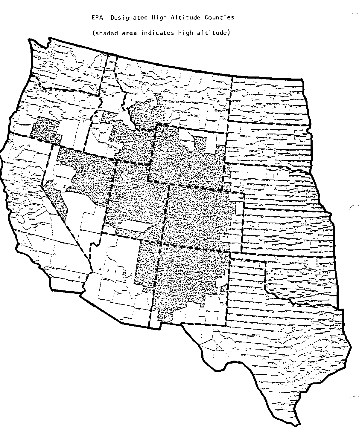
COUNTIES WHICH ARE DESIGNATED HIGH-ALTITUDE AREAS
ARIZONA MONTANA UTAH
Apache Navajo Beaverhead Madison Beaver Morgan Cochise Yavapai Deer Lodge Meagher Box Elder Piute Coconino Gallatin Park Cache Rich Jefferson Silver Bow Carbon Salt Lake COLORADO Judith Basin Wheatland Daggett San Juan Powell Davis San Pete Adams Kit Carson Duschesne Sevier Alamosa Lake NEBRASKA Emery Summit Arapahoe LaPlata Garfield Tooele Archuleta Larimer Banner Kimball Grand Unitah Boulder Las Animas Cheyenne Sioux Iron Utah Chaffee Lincoln Juab Wasatch Cheyenne Mesa NEVADA Kane Wayne Clear Creek Mineral Millard Weber Conejos Moffat Carson City Lyon Costilla Montezuma Douglas Mineral WYOMING Crowley Montrose Elko Nye Custer Morgan Esmeralda Pershing Albany Natrona Delta Otero Eureka Storey Campbell Niobrara Denver Ouray Humboldt Washoe Carbon Park Dolores Park Lander White Pine Converse Platte Douglas Pitkin Lincoln Fremont Sublette Eagle Pueblo Goshen Sweetwater Elbert Rio Blanco NEW MEXICO Hot Springs Teton El Paso Rio Grande Johnson Vinta Fremont Routt Bernalillo Mora Laramie Washakie Garfield Saguache Catron Rio Arriba Lincoln Weston Gilpin San Juan Colfax Roosevelt Grand San Miguel Curry Sandoval Gunnison Summit DeBaca San Juan Hinsdale Teller Grant Sans Miguel Huerfano Washington Guadalupe Santa Fe Jackson Weld Harding Sierra Jefferson Hidalgo Socorro Lincoln Taos IDAHO Los Alamos Torrance Luna Union Bannock Franklin McKinley Valencia Bear Lake Fremont Otero Bingham Jefferson Blaine Lemhi OREGON Booneville Madison Butte Minidoka Harney Lake Camas Oneida Klamath Caribou Power Cassia Teton TEXAS Clark Valley Custer Jeff Davis Hudspeth Parmer
General Motors bulletins are intended for use by professional technicians, not a "do-it-yourselfer". They are written to inform those technicians of conditions that may occur on some vehicles, or to provide information that could assist in the proper service of a vehicle. Properly trained technicians have the equipment, tools, safety instructions and know-how to do a job properly and safely. If a condition is described, do not assume that the bulletin applies to your vehicle, or that your vehicle will have that condition. See a General Motors dealer servicing your brand of General Motors vehicle for information on whether your vehicle may benefit from the information.
