Tools Required
| • | J 36462 Engine
Support Adapter Leg |
| • | J 35953 Engine
Support Foot Modification |
Removal Procedure
- Remove the air cleaner duct. Refer to Engine Controls.
- Drain the coolant. Refer to Cooling and Radiator.
- Remove the coolant recovery reservoir. Refer to Cooling and Radiator.
- Install the J 28467-360
.
- Install the J 28467-90
.
- Install the J 36462
.
- Install the J 35953
.
- Raise the vehicle. Suitably support the vehicle. Refer to General
Information.
- Remove the right front wheel. Remove the left front wheel. Refer
to Tires and Wheels.
- Drain the oil pan.
- Remove the steering gear retaining bolts. Hang the steering gear
on the body. Refer to Power Steering Gear and Pump.
- Remove the right and the left lower ball joint nuts. Separate
the lower ball joints from the control arms. Refer to Front Suspension.
- Remove the power steering cooler line clamps at the frame. Refer
to Power Steering Gear and Pump.
- Remove the engine mount nuts at the frame. Support the frame.
Refer to
Engine Mount Replacement
.
- Remove the frame retaining bolts. Refer to Body Dimensions and
Underbody.
- Remove the frame. Refer to Body Dimensions and Underbody.

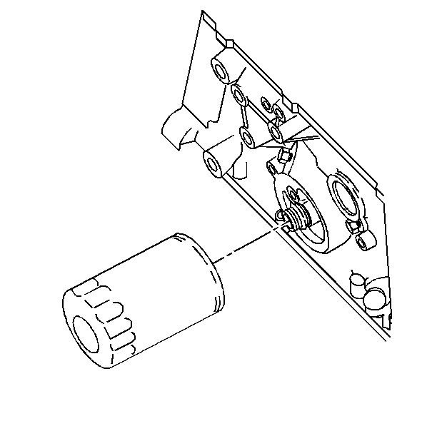
- Remove the engine oil
filter.
- Remove the engine oil cooler. Refer to
Engine Oil Cooler Replacement
.
- Remove the engine oil level sensor. Refer to Engine Controls.
- Remove the starter motor. Refer to Engine Electrical.
- Remove the flywheel cover. Refer to Automatic Transaxle.

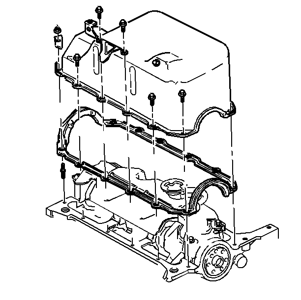
- Remove the oil pan retaining
nuts and bolts.
- Remove the oil pan.
- Remove the oil pan gasket.
- Clean the following parts:
| • | The rear main bearing cap |
Installation Procedure

- Apply sealer GM P/N 12345739
to the tabs of the gasket that insert next to the rear main bearing cap notches.
- Install the new gasket.
- Install the oil pan.
Notice: Use the correct fastener in the correct location. Replacement fasteners
must be the correct part number for that application. Fasteners requiring
replacement or fasteners requiring the use of thread locking compound or sealant
are identified in the service procedure. Do not use paints, lubricants, or
corrosion inhibitors on fasteners or fastener joint surfaces unless specified.
These coatings affect fastener torque and joint clamping force and may damage
the fastener. Use the correct tightening sequence and specifications when
installing fasteners in order to avoid damage to parts and systems.
- Install the oil pan
mounting nuts.
Tighten
Tighten the nuts to 11 N·m (97 lb in).
- Install the oil pan mounting bolts.
Tighten
- Tighten the rear bolts to 27 N·m (20 lb ft).
- Tighten the remaining bolts to 11 N·m (97 lb in).
- Install the flywheel cover. Refer to Automatic Transaxle.
- Install the engine oil level sensor. Refer to Engine Controls.
- Install the starter motor. Refer to Engine Electrical.
- Install the engine oil cooler. Refer to
Engine Oil Cooler Replacement
.

- Install the engine oil
filter.
- Install the frame. Support the frame. Refer to Body Dimensions
and Underbody.
- Install the frame retaining bolts. Remove the frame support. Refer
to Body Dimensions and Underbody.
- Install the engine mount nuts at the frame. Refer to
Engine Mount Replacement
.
- Install the power steering cooler line clamps at the frame. Refer
to Power Steering Gear and Pump.
- Install the ball joints on the control arms. Refer to Front Suspension.
- Install the steering gear on the steering gear mounts. Refer to
Power Steering Gear and Pump.
- Install the right front wheel. Install the left front wheel. Refer
to Tires and Wheels.
- Lower the vehicle.
- Remove the J 28467-360
.
- Remove the J 28467-50
.
- Remove the J 36462
.
- Remove the J 35953
.
- Install the air cleaner duct. Refer to Engine Controls.
- Fill the crankcase with clean engine oil. Refer to Maintenance
and Lubrication.


