Tools Required
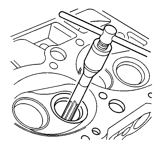
| • | J 38978
Valve
Guide Reamer for 0.127 mm (OS Valve) |

- Inspect the cylinder head gasket and the cylinder head mating surfaces for
any of the following conditions:
- If the cylinder head gasket has failed, determine the cause from
the following list of conditions:
| • | An improper installation |
| • | A loose or wrapped cylinder head |
| • | A missing or not fully seated dowel pin |
| • | A low torque on the cylinder head bolts |
| • | A warped cylinder block |
| • | A scratched cylinder head surface |
| • | An excessive inlet manifold torque |
| • | A cracked engine block tapped hole |
Important: Do not use a motorized wire brush on any gasket sealing surface. Do
not scratch the valve stem surface when using a wire brush. Do not attempt
to weld the cylinder head. Replace the cylinder head if necessary.
- Clean the cylinder head bolts.
- Clean the cylinder head. Do this by removing any varnish, carbon,
and soot the bare metal.
- Use a suitable tool in order to clean the valve guides.
- Use a wire brush in order to remove any carbon from the valves.
- Soak the valve in a carburetor cleaning fluid in order to remove
any varnish.
- Clean the threaded holes on the cylinder head.
- Inspect the cylinder head deck for signs of corrosion, sand intrusion,
and porosity.
- Inspect the cylinder head for cracks, especially between the valve
seats and the exhaust ports.

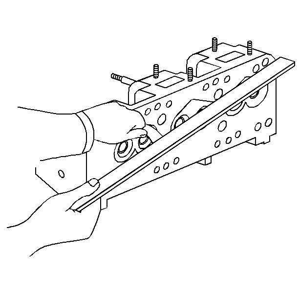
- Inspect the cylinder head deck and the intake and exhaust manifold surfaces
for flatness.
| 11.1. | If the mating surfaces are out of flat by more than 0.1 mm
(0.004 in), mill the surfaces. |
| 11.2. | Replace the cylinder head if more than 0.25 mm (0.010 in)
of the metal must be removed. |
- Inspect all of the threaded holes for damage. If necessary, recondition
the threads with thread inserts.
- Inspect the cooling jacket plug seating surfaces.
- Inspect the valve seats for excessive wear or burn spots. Properly
clean the valve guide if the valve seats need reconditioning.
- If the valve guide needs reaming, measure the valve guide clearance
in order to determine if an oversized valve is required.
- If a valve is burnt, recondition the valve seat insert. Do this
by grinding the valve seat.
| 16.1. | Do not remove more than 2 mm (0.079 in) of the valve
seat material. |
| 16.2. | If the new valve seat is too wide after grinding, narrow the valve
seat by using a 70 degree stone. |
- Inspect the valve stem tip for signs of wear.
- Inspect the valve lock and the oil seal grooves for chipped or
worn lands. Replace the valve if any of these conditions are found.
- Inspect the valve face for signs of burning or cracking. If pieces
of the face are broken off, inspect the corresponding piston and the cylinder
head for signs of damage.
- Inspect the valve stem for burrs or scratches. Remove any burrs
or scratches with an oil stone.
- Inspect the valve stem for straitness. Do this by using V blocks.
- Inspect the valve head for bending or distortion. Replace any
bent or distorted valves.

- Inspect the valve face for grooves. If a groove is so deep that refacing
the valve would result in a knife edge, replace the valve.
- Grind the valve face to specifications if the valve face is otherwise
in good condition. Replace the valve if the valve face cannot be ground within
specifications.
- Inspect the valve spring dampers for any broken pieces or cracks.
Replace the valve spring dampers if any of these conditions are found.

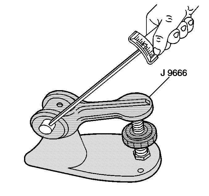
- Inspect the valve springs for free length.
- Inspect the valve springs for bent spring end.
- Inspect for cracked or broken valve springs.

- Inspect for low spring tension (load open and closed)
- Replace the valve spring if any of the above conditions are found.
- Inspect the valve spring seating surface of the spring caps for
signs of wear, cracks, and gouging. Replace the seating surface if any of
these conditions are found.
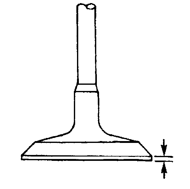
- Measure the valve margin after grinding the valves. Replace the
valve if the margin is less than the minimum recommended margin.

- Measure the valve guide clearance. Do this by using one of the following methods:
| • | Insert the valve into its guide. Lift the valve 2 mm (1/8 in)
off of the seat. Move the valve from side to side while measuring the amount
of movement with a dial indicator. |
| • | Measure the guide ID with a hole gauge. Measure the valve stem
with a micrometer. Compare both of the measurements. |
Notice: Clean the valve guides before reaming. Packing of chips or carbon may
result in the reamer jamming into the valve guide or broken reamer flutes.

- If necessary, ream the valve guide oversize and install an oversize valve.


