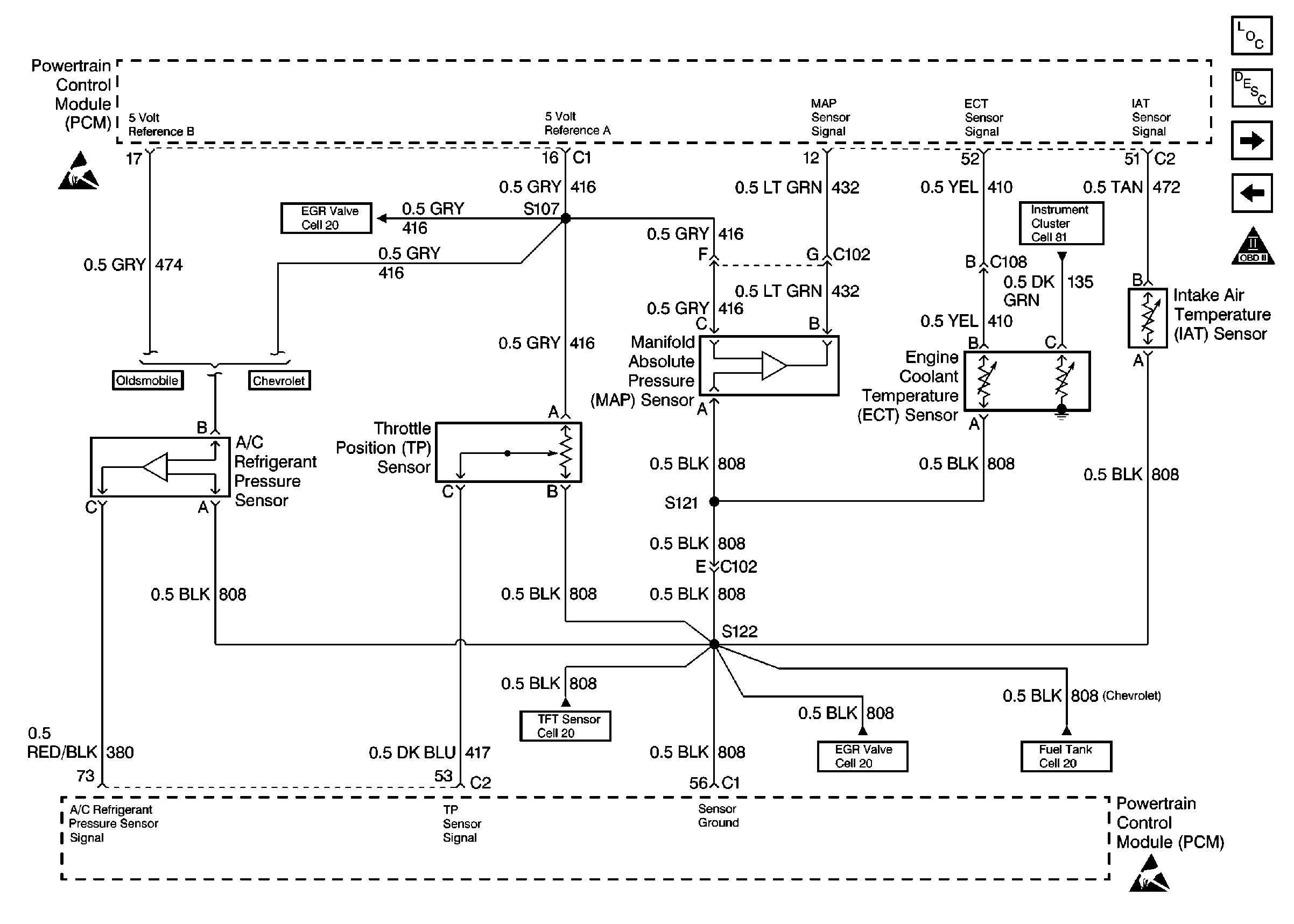
Refer to
Engine Data Sensors-A/C Refrig Press, TP, MAP, ECT, IAT

Circuit Description
To provide the best possible combination of driveability, fuel economy, and emission control, a closed loop air/fuel metering system is used. When the vehicle is first started, the PCM controls fuel delivery in open loop, ignoring the HO2S signals and calculating air/fuel ratio based on inputs from the engine coolant temperature, throttle position, and mass air flow sensors. The PCM will begin using the HO2S 1 signal for controlling fuel delivery (Closed Loop) when the following conditions have been met:
| • | The HO2S output signal is varying, indicating that the sensor is hot enough to operate properly. |
| • | The Engine Coolant Temperature sensor indicates coolant temperature above 21°C (70°F). |
| • | Time since start-up is at least 15 seconds for a warm engine or 90 seconds for a cold engine. |
Conditions for Setting the DTC
| • | No active IAT or ECT DTC(s) present. |
| • | Start-up intake air temperature is greater than 18°C (68°F). |
| • | Start-up engine coolant temperature is between 0°C (32°F) and 21°C (70°F). |
| • | Engine coolant temperature sufficient to allow Closed Loop operation (21°C /70°F) is not achieved within 2 minutes of start-up. |
Action Taken When the DTC Sets
| • | The PCM will illuminate the malfunction indicator lamp (MIL) during the second consecutive trip in which the diagnostic test has been run and failed. |
| • | The PCM will store conditions which were present when the DTC set as Freeze Frame and Failure Records data. |
Conditions for Clearing the MIL/DTC
| • | The PCM will turn OFF the MIL during the third consecutive trip in which the diagnostic has been run and passed. |
| • | The History DTC will clear after 40 consecutive warm-up cycles have occurred without a malfunction. |
| • | The DTC can be cleared by using the scan tool. |
Diagnostic Aids
DTC P0125 set indicates a skewed ECT sensor. Comparing the engine coolant temperature displayed on a scan tool with actual coolant temperature measured with a thermometer may isolate this condition. If the displayed engine coolant temperature is not close to the actual coolant temperature, replace the ECT sensor.
Check for the following conditions:
| • | Poor connection at PCM. Inspect harness connectors for backed out terminals, improper mating, broken locks, improperly formed or damaged terminals, and poor terminal to wire connection. |
| • | Damaged harness. Inspect the wiring harness for damage. If the harness appears to be OK, observe the display on the scan tool while moving connectors and wiring harnesses related to the sensor. A change in the display will indicate the location of the fault. |
If DTC P0125 cannot be duplicated, the information included in the Fail Records data can be useful in determining vehicle mileage since the DTC was last set.
Test Description
The number below refers to the step number on the Diagnostic Table:
Step | Action | Value(s) | Yes | No |
|---|---|---|---|---|
1 | Was the Powertrain On-Board Diagnostic Check performed? | -- | ||
Does Eng. Cool. Temp. increase to above the specified value within 9 minutes? | 21°C (70°F). | Refer to Diagnostic Aids | ||
3 | Are any ECT sensor DTCs set? | -- | Go to applicable ECT sensor DTC chart | |
4 |
Are the cooling fans off? | -- | Go to Electric Cooling Fan Diagnosis or Electric Cooling Fan Diagnosis | |
5 | Check the cooling system coolant level. (Refer to Cooling and Radiator). Is the coolant level OK? | -- | ||
6 | Check for proper operation of the thermostat (refer to Cooling and Radiator). Is the thermostat operating correctly? | -- | ||
7 | Compare Eng. Cool. Temp. displayed on the scan tool to the actual coolant temperature measured with a thermometer. Is the scan tool Eng. Cool. Temp. indication close to the measured temperature? | -- | ||
8 | Check for high resistance in wiring related to the ECT sensor. Also, check for poor connections at ECT sensor and PCM. Was a problem found? | -- | ||
9 | Refer to Cooling and Radiator for cooling system diagnosis and repair condition as necessary. Is action complete? | -- | -- | |
10 | Replace the faulty terminal(s) or repair faulty wiring as necessary (refer to Engine Electrical). Is action complete? | -- | -- | |
11 | Replace ECT sensor. Is action complete? | -- | -- | |
12 |
Does Eng. Cool. Temp. increase to above the specified value within 9 minutes? | 21°C (70°F) | Repair complete |
