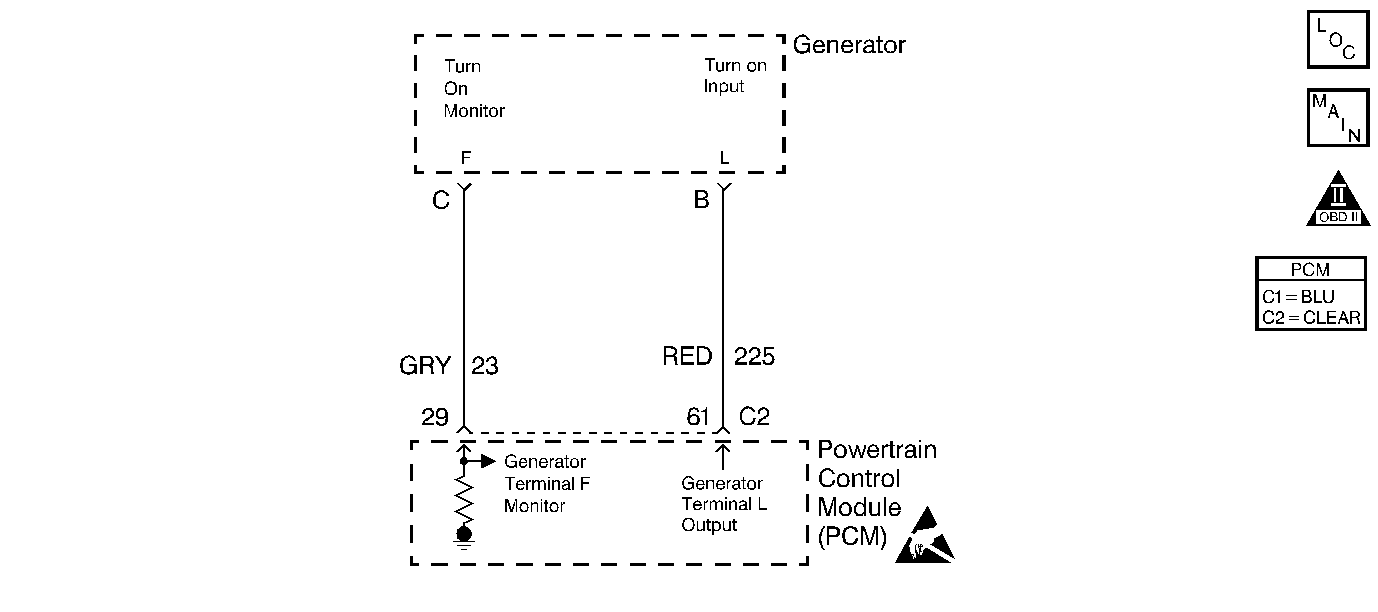
Powertrain Control Module Controlled Generator Diagnosis L Terminal Circuit

Circuit Description
When the ignition switch is in the Run position, the PCM supplies voltage to the L terminal of the generator, turning on the digital voltage regulator. When the engine is started, the regulator senses the AC output of the stator via an internal circuit. The regulator will then control the output of the generator by pulse width modulating the field current. This PWM signal is fed back to the PCM on the F terminal circuit. The PCM monitors generator output using this signal. The PCM controls the charge warning indicator in the I/P via Class 2 serial data.
Diagnostic Aids
A generator fault, such as a shorted output diode, malfunctioning regulator, open or shorted rotor, or open sense lead may cause a low battery charge. Refer to Charging System Check for further information and generator diagnosis.
Use a scan tool in order to diagnosis the generator circuits. A scan tool displays Commanded GEN Off when there is a problem with the L-terminal circuit.
L Terminal Circuit and F Terminal Circuit shorted together causes GEN PWM to remain fixed at approximately 25%.
Test Description
The numbers below refer to the step numbers on the Diagnostic Table.
-
This isolates if the generator is at fault or if the PCM and wiring are at fault.
-
A poor connection at the generator will cause a no output condition.
Step | Action | Value(s) | Yes | No |
|---|---|---|---|---|
1 | Did you perform the Powertrain On-Board Diagnostic (OBD) System Check? | -- | ||
|
Important: This table assumes there is a charging system problem. Before proceeding with this table check the generator output.
Is the voltage near the value specified? | 5V | |||
3 |
Does the circuit have continuity to ground? | -- | ||
4 | Check the resistance of the L Terminal circuit between Pin B in the generator harness connector and the PCM harness connector. Is the resistance the same or less than the value specified? | 5ohms | ||
5 | Repair the L Terminal circuit shorted to ground. Is the action complete? | -- | System OK | -- |
6 | Repair the open/high resistance L Terminal circuit. Is the action complete? | -- | System OK | -- |
7 | Check for poor connections/terminal tension at the PCM. Refer to Intermittents and Poor Connections Diagnosis . Was a problem found and corrected? | -- | System OK | |
8 | Replace the PCM. Refer to Powertrain Control Module Replacement/Programming . Is the action complete? | -- | System OK | -- |
Check for poor connections/terminal tension at the Generator. Refer to Intermittents and Poor Connections Diagnosis . Was a problem found and corrected? | -- | System OK | ||
10 | Repair or replace the Generator. Refer to Generator Replacement . Is the action complete? | -- | System OK | -- |
Powertrain Control Module Controlled Generator Diagnosis F Terminal Circuit

Circuit Description
The F-terminal circuit from the generator is a pulse width modulation (PWM) signal to the PCM from the digital voltage regulator. The pulse width of the signal is proportional to generator output. The PCM monitors the PWM frequency to determine electrical load on the charging system.
Diagnostic Aids
A generator fault, such as a shorted output diode, malfunctioning regulator, an open or shorted rotor, or an open sense lead may cause a low battery charge. Refer to Charging System Check for further information and generator diagnosis.
F Terminal Circuit shorted to B+ causes GEN PWM to be fixed at approximately 70 %.
Step | Action | Value(s) | Yes | No |
|---|---|---|---|---|
1 | Did you perform the Powertrain On-Board Diagnostic (OBD) System Check? | -- | ||
2 |
Does the scan tool display the specified value? | 0% | ||
3 | Does the scan tool display the specified value? | 100% | System OK | |
4 |
Does the parameter change from 0% to 100%? | -- | ||
5 |
Does the DMM indicate the same or less than the specified value? | 5 ohms | ||
6 | Check for continuity from Pin C to battery ground in the generator harness connector using the DMM J 39200 . Does the DMM indicate continuity? | -- | ||
7 | Disconnect the generator harness connector. Does the scan tool display the specified value? | 0% | ||
8 | Repair the F Terminal circuit shorted to voltage. Is the action complete? | -- | System OK | -- |
9 | Repair the open/high resistance F Terminal circuit. Is the action complete? | -- | System OK | -- |
10 | Repair the F Terminal circuit shorted to ground. Is the action complete? | -- | System OK | -- |
11 | Check for poor connections/terminal tension at the Generator. Refer to Intermittents and Poor Connections Diagnosis . Was a problem found and corrected? | -- | System OK | |
12 | Repair or replace the Generator. Refer to Generator Replacement . Is the action complete? | -- | System OK | -- |
13 | Check for poor connections/terminal tension at the PCM. Refer to Intermittents and Poor Connections Diagnosis . Was a problem found and corrected? | -- | System OK | |
14 | Replace the PCM. Refer to Powertrain Control Module Replacement/Programming Is the action complete? | -- | System OK | -- |
