The fuel metering system starts with the fuel in the fuel tank. An electric
fuel pump, located in the fuel tank with the gauge sending unit, pumps fuel
to the fuel rail through an in-line fuel filter. The fuel pump is designed
to provide fuel at a pressure above the pressure needed by the fuel injectors.
A fuel pressure regulator in the fuel rail keeps fuel available to the
fuel injectors at a constant pressure. Unused fuel is returned to the fuel
tank by a separate pipe. For further information on the fuel tank, in-line
filter, and fuel pipes. Refer to
Fuel Supply Component Description
.
The fuel feed pipe delivers the fuel from the fuel tank to the fuel
rail assembly. The fuel feed pipe carries excess fuel from the outlet port
of the fuel rail back to the fuel tank. The canister purge pipe transfers
fuel vapors to the charcoal canister.
The fuel feed, return, vacuum and EVAP pipes are assembled as a harness.
Retaining clips hold the pipes together and provide a means for attaching
the pipes to the vehicle. Quick-connect type fittings are used at the ends
of the fuel feed and return and at the in-line fuel filter. They are described
below. Sections of the pipes that are exposed to chafing, high temperature
or vibration are protected with heat resistant rubber hose and/or coextruded
conduit.
Nylon fuel pipes are designed to perform the same function as the steel
or rubber fuel pipes they replace. Nylon pipes are constructed to withstand
maximum fuel system pressure, exposure to fuel additives, and changes in
temperature. Both fuel feed and fuel return pipe size is 5/16 OD. The EVAP
pipe from tank to canister size is 1/4 OD and from canister to engine is
5/16 OD. The vacuum signal pipe is 1/4 ID. Nylon fuel pipes are somewhat
flexible and can be formed around gradual turns under the vehicle. However,
if forced into sharp bends, nylon pipes will kink and restrict fuel flow.
Also, once exposed to fuel, nylon pipes may become stiffer and more likely
to kink if bent too far. Special care should be taken when working on a
vehicle with nylon fuel pipes.
Quick-connect type fittings provide a simplified means of installing
and connecting fuel system components. There are two types of quick-connect
fittings, each used at different locations in the fuel system. Each type
consists of a unique female socket and a compatible male connector. O-rings,
located inside the female socket, provide the fuel seal. Integral locking
tabs or fingers hold the fittings together. The quick-connect fittings used
at the fuel filter and other connections at the rear of the vehicle have
hand releasable locking tabs. The fittings used at the engine fuel pipes
have locking tabs that require a special tool to release.
The Mass Air Flow (MAF) sensor is located in the MAF sensor between
the air snorkel and the throttle body. It senses the amount of air entering
the intake manifold. This information is required by the PCM to control fuel
and emissions.
The MAF sensor used on this vehicle is a hot wire type and is used to
measure air flow rate (mass/unit time). The MAF sensor output is a variable
frequency square wave based on air mass traveling through the sensor. A low
frequency output signal from the MAF sensor indicates low air flow and high
frequency indicates high air flow. The MAF sensor has two wires crossing
the air stream through it. One senses ambient temperature and the other,
the hot wire, is kept at a fixed temperature above the ambient temperature.
The MAF sensor senses air flow by measuring the power necessary to keep
the hot wire hot, which is proportional to air flow, and converts it to
a frequency modulate output signal.
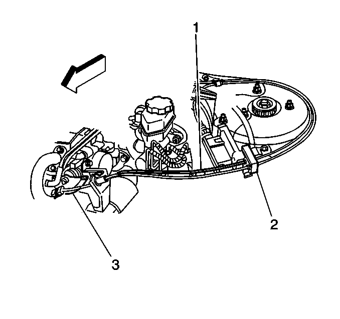
The accelerator control
system is cable-type. There are no linkage adjustments. Therefore, the specific
accelerator control cable (3) must be used. The accelerator control (3) and
cruise control (1) cables are attached to a retainer (2).


