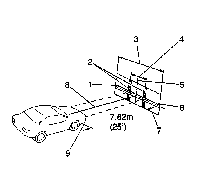
The headlamp assemblies must be aimed for proper illumination of the road. The headlamp assembly aim should be checked when a new headlamp assembly is installed, or if service or repairs in the front end area may have disturbed the headlamp mounting brackets.
Horizontal and vertical aiming of each of the composite headlamps is done by turning adjusting screws which move the headlamp capsule in relation to the headlamp housing assembly. The horizontal adjustment screw (1) is located on the rear upper edge of each of the headlamp assemblies, toward the outboard side of the vehicle. The vertical adjustment screw (4) is located on the rear upper edge of each of the headlamp assemblies, toward the center of the vehicle.
Some state and local authorities have specific requirements for aiming the headlamps. These requirements must be followed.
Aiming Area Preparation
Choose an appropriate aiming area, then prepare the aiming screen as described in the following.
| • |

|
| • |
| • |
| • |
Important: For each vehicle checked, the horizontal line or tape (1) on the screen must be adjusted. Vehicles of the same model and year may have different standing height for the headlamp capsules. |
| • | If a regular commercial aiming screen is not available, the screen may consist of a vertical wall having a clear uninterrupted area at least 1.83 m (6 ft) high by 3.66 m (12 ft) wide, finished with a washable non-gloss white paint. |
Vehicle Preparation
Prepare the vehicle for checking the headlamp beam aim as follows:
- Make sure that all the components are in place on the vehicle, if other service has been performed on the vehicle.
- Make sure the fuel level is 1/2 full or less.
- Make sure the tires are inflated to the proper pressures.
- Stop all other operations of work on the vehicle.
- Position the vehicle so it is square with the aiming screen, and with the headlamp capsule lenses directly over the reference line (9) which has been painted or taped on the floor.
- Locate the vertical center line on the aiming screen (5) so that it is in line with the center of the vehicle (8). This can be accomplished by sighting through the center of the rear window and over the hood.
- Close the doors.
- Rock the vehicle sideways to stabilize the suspension.
- Measure the height from the floor to the horizontal center of a headlamp assembly low beam bulb. Adjust the horizontal tape on the aiming screen (1) to match this dimension.
- Measure the distance between the centerline of the right headlamp assembly low beam bulb and the center of the left headlamp assembly low beam bulb. Position the vertical tapes on the aiming screen (2) this distance to the right and left of the screen centerline (4).

Mark the vertical center of the front and rear windows with narrow tape. Use these marks as sights to locate the centerline of the vehicle. Move the vehicle or the screen until the center line of the screen comes into alignment with the two points.
Adjustment Procedure
- Raise the hood.
- Turn ON the low beam lamps.
- Inspect the horizontal aim.
- Adjust the aim using the horizontal adjusting screw, to align the left edge of the high intensity zone with the headlamp low beam bulb vertical centerline (1), within the range of 102 mm (4 in) to the left (4) of the lamp bulb vertical centerline (1), to 102 mm (4 in) to the right (3) of the lamp bulb vertical centerline (1) on the aiming screen.
- Inspect the vertical aim.
- Adjust the aim using the vertical adjusting screw, to align the top edge of the high intensity zone to the headlamp low beam bulb horizontal centerline (2), within the range of 51 mm (2 in) above (6) the lamp bulb horizontal centerline (2), to 64 mm (2.5 in) below (5) the lamp bulb horizontal centerline (2) on the aiming screen.
- Turn OFF the headlamps.
- Lower the hood.

