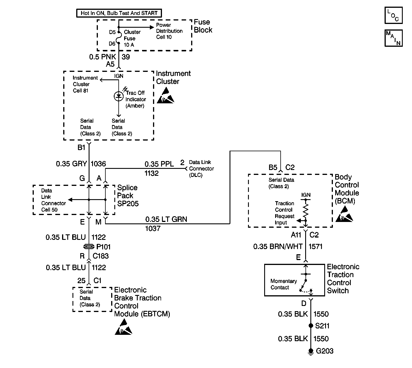
Circuit Description
The TRAC OFF Indicator is controlled by the EBTCM by sending class 2 messages to the Instrument Panel Cluster (IPC). It is turned on when the EBTCM sets a DTC that turns on the TRAC OFF indicator. It is also turned on or off when the Traction Control Switch is pressed. The Body Control Module (BCM) receives the input from the Traction Control Switch, the BCM then sends a class 2 message to the EBTCM telling the EBTCM the state of the switch. The BCM supplies 12 volts to the TCS switch, when the TCS switch is pressed the BCM sees the voltage go low and sends the EBTCM the message that the TCS switch state has changed. When the EBTCM receives the message from the BCM that the switch state has changed, the EBTCM turns on or off Traction Control and sends a message to the IPC to turn on or off the TRAC OFF indicator depending on its previous state.
Test Description
The numbers below refer to step numbers on the diagnostic table.
-
Checks if the Body Control Module is receiving a Traction Control Switch input.
-
Checks if the EBTCM is receiving a Traction Control Switch message from the Body Control Module.
-
Checks if the Body Control Module or the Traction Control Switch is at fault.
Step | Action | Value(s) | Yes | No |
|---|---|---|---|---|
DEFINITION: The TRAC OFF indicator does not come on when the Traction Control Switch is pressed to disable the Traction Control System. | ||||
1 | Was the ABS Diagnostic System Check performed? | -- | ||
Does the TCS Switch state change properly as the switch is pressed and released? | -- | |||
Using a scan tool in ABS/TCS Data Display, read the TCS Switch Status as you press and release the TCS Switch. Does the TCS Switch state change properly as the switch is pressed and released? | -- | |||
4 | Replace the EBTCM. Refer to Electronic Brake and Traction Control Module Replacement . Is the replacement complete? | -- | -- | |
5 | Using a scan tool in the Instrument Panel (IPC) Special Functions attempt to turn the TRAC OFF indicator on. Did the TRAC OFF indicator turn on? | -- | ||
6 |
Is the TRAC OFF indicator bulb OK? | -- | ||
7 | Replace the TRAC OFF Indicator bulb. Refer to Instrument Cluster Bulb Replacement in Instrument Panel, Gauges and Console. Is the replacement complete? | -- | -- | |
8 | Replace the Instrument Panel Cluster. Refer to Instrument Cluster Replacement in Instrument Panel, Gauges and Console. Is the replacement complete? | -- | -- | |
Does the TCS Switch status read pressed with the jumper wire connected? | -- | |||
10 | Replace the Traction Control Switch. Refer to Electronic Traction Control Switch Replacement in Instrument Panel Gauges and Console. Is the replacement complete? | -- | -- | |
11 |
Is the resistance within the range specified in the value(s) column? | 0-5ohms | ||
12 | Repair CKT 1550 for an open or high resistance. Refer to Wiring Repairs in Wiring Systems. Is the repair complete? | -- | -- | |
13 |
Is the resistance within the range specified in the value(s) column? | 0-5ohms | ||
14 | Repair CKT 1571 for an open or high resistance. Refer to Wiring Repairs in Wiring Systems. Is the repair complete? | -- | -- | |
15 | Replace the Body Control Module. Refer to Body Control Module Replacement in Body Control System. Is the replacement complete? | -- | -- | |
