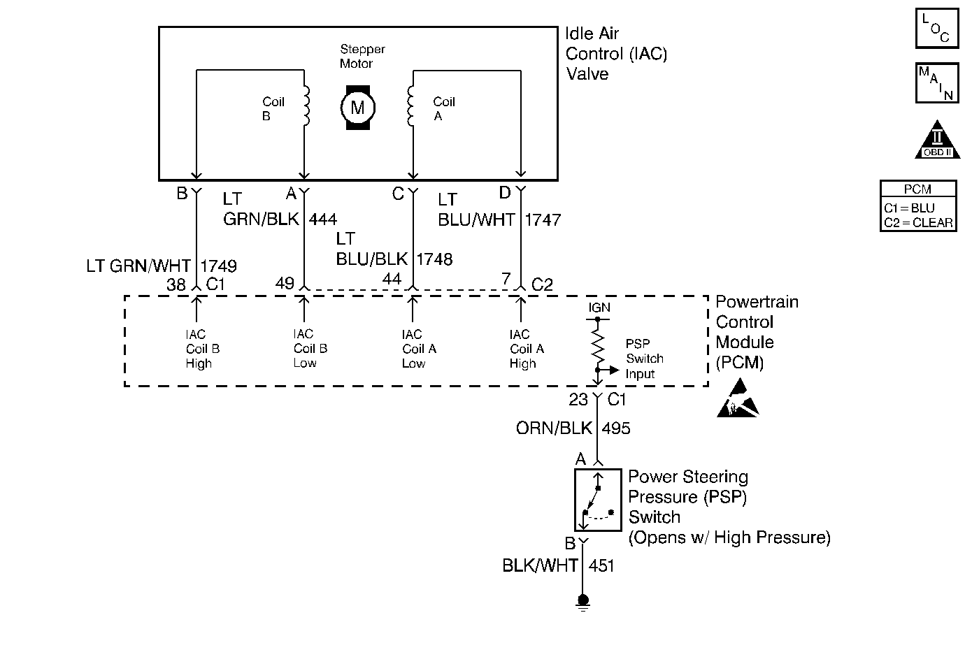
Circuit Description
The Power Steering Pressure (PSP) switch is a normally closed switch which opens when power steering pressure exceeds 450 to 650 psi. The PSP switch closes again when pressure drops below 100 to 450 psi. The PCM pulls the PSP signal circuit up to approximately 12 volts. This diagnostic test monitors the voltage on the PSP switch signal circuit. During power steering no-load condition, the PSP switch is closed causing the signal voltage to be pulled low. When a load is placed on the power steering such as during low speed parking maneuvers or at full steering lock, the switch opens and the PCM will detect 12 volts on the signal circuit. The PCM uses this information to adjust idle speed when the additional load is present.
Conditions for Running the DTC
| • | Engine running. |
| • | Vehicle speed 45 MPH or greater. |
Conditions for Setting the DTC
PSP signal voltage high for 60 seconds.
Action Taken When the DTC Sets
| • | The powertrain control module (PCM) stores the DTC information into memory when the diagnostic runs and fails. |
| • | The malfunction indicator lamp (MIL) will not illuminate. |
| • | The PCM records the operating conditions at the time the diagnostic fails. The PCM stores this information in the Failure Records. |
Conditions for Clearing the MIL/DTC
| • | A History DTC will clear after forty consecutive warm-up cycles, if no failures are reported by this or any other non-emission related diagnostic. |
| • | A last test failed (Current DTC) will clear when the diagnostic runs and does not fail. |
| • | Use a scan tool in order to clear the MIL/DTC. |
| • | Interrupting the PCM battery voltage may or may not clear DTCs. This practice is not recommended. Refer to Powertrain Control Module Description , Clearing Diagnostic Trouble Codes. |
Diagnostic Aids
Notice: Use the connector test adapter kit J 35616-A for any test that
requires probing the following items:
• The PCM harness connectors • The electrical center fuse/relay cavities • The component terminals • The component harness connector
Check for intermittent contact at the power steering pressure switch. Engine torque/movement stretching the harness could be causing an intermittent open circuit.
If the problem is intermittent, refer to Intermittent Conditions .
Test Description
Number(s) below refer to the step number(s) on the Diagnostic Table.
-
This is a functional test of the switch. This DTC only detects high signal voltage (open signal or ground circuits, switch stuck open). If the display always indicates Normal, check for the signal circuit shorted to ground or a stuck closed switch.
-
If display always says Hi Press., proceed with circuit diagnosis. If the display indicates Hi Press. with the engine running, and Normal with the key on, engine off, with no steering load, there may be a problem causing excessive pressure in the power steering system.
Step | Action | Value(s) | Yes | No |
|---|---|---|---|---|
1 | Did you perform the Powertrain On-Board Diagnostic (OBD) System Check? | -- | ||
Did display change from Normal to Hi Press. and back to Normal? | -- | Refer to Diagnostic Aids. | ||
Turn the engine off, then turn the key to On. Does the display remain Hi Press.? | -- | Go to the Power Steering System Test in Power Steering | ||
4 |
Is the voltage the same or more than the value specified? | 10 volts | ||
5 | Jumper power steering pressure switch connector terminals A and B together (harness side). Does the display read Normal? | -- | ||
6 |
Is continuity indicated? | -- | ||
7 | Repair the open/high resistance signal circuit. Is the action complete? | -- | -- | |
8 | Repair the open/ high resistance ground circuit. Is the action complete? | -- | -- | |
9 | Check for poor connections/terminal tension at the PSP switch. Refer to Intermittents and Poor Connections Diagnosis . Was a problem found and corrected? | -- | ||
10 | Check for poor connections/terminal tension at the PCM. Refer to Intermittents and Poor Connections Diagnosis . Was a problem found and corrected? | -- | ||
11 | Replace the PSP switch. Is the action complete? | -- | -- | |
12 | Replace the PCM. Important:: The replacement PCM must be programmed. Refer to Powertrain Control Module Replacement/Programming Is the action complete? | -- | -- | |
13 |
Does the scan tool indicate that this test ran and passed? | -- | ||
14 | Review Captured Info using the scan tool. Are there any DTCs that have not been diagnosed? | -- | Go to the applicable DTC table
| System OK |
