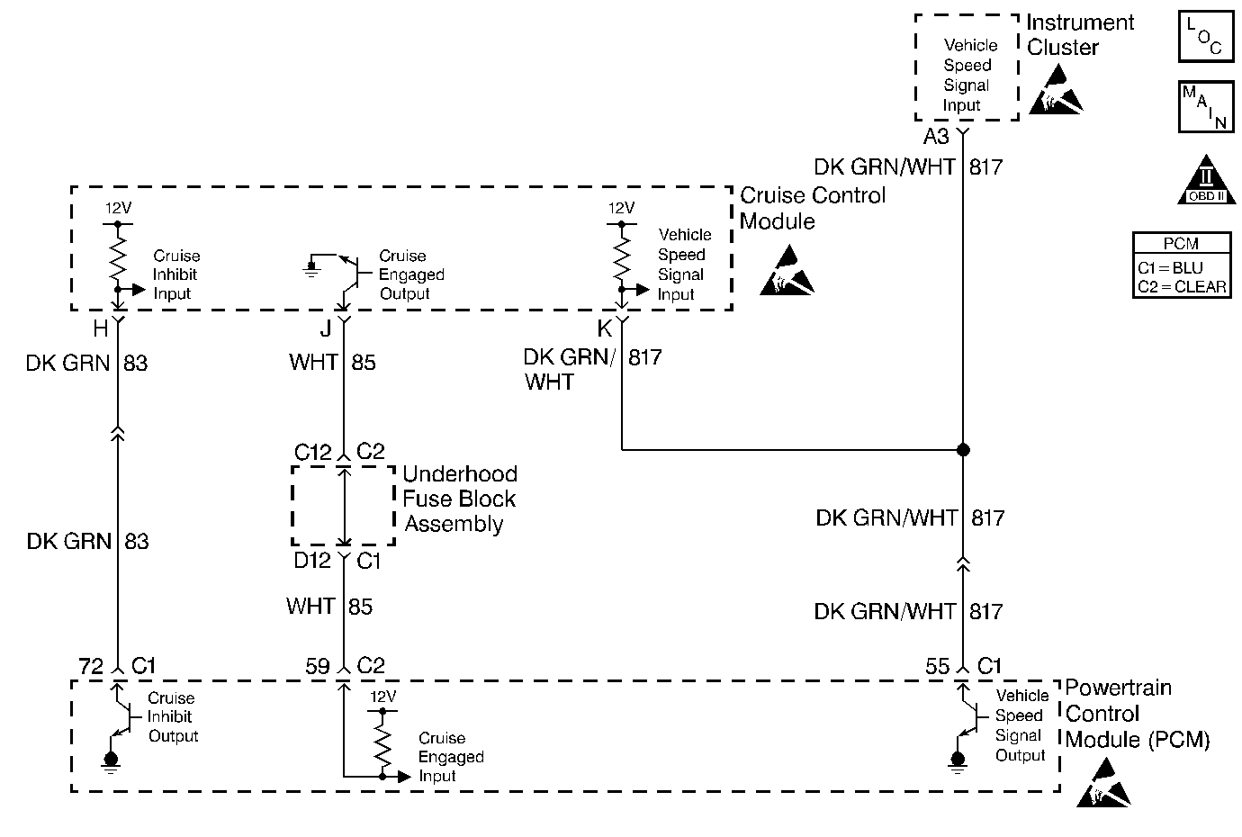
Circuit Description
The Cruise Control module pulls the Cruise Inhibit circuit up to approximately 12 volts. When the PCM determines that cruise control is allowed, the PCM grounds the Cruise Inhibit circuit. The Cruise Control module detects the low voltage signal and enables the system. The PCM grounds the cruise inhibit circuit via an internal solid state device called a driver. The primary function of the driver is to supply the ground for the component being controlled. Each driver has a fault line which is monitored by the PCM. If the fault detection circuit senses a voltage other than what is expected, this DTC will set.
Conditions for Running the DTC
| • | The ignition voltage is between 9-18 volts. |
| • | The engine speed is more than 80 RPM. |
| • | The PCM driver transitions from ON to OFF or from OFF to ON. |
Conditions for Setting the DTC
| • | A short to ground, an open circuit, or a short to battery voltage is detected on the control circuit. |
| • | The condition is present for at least 30 seconds. |
Action Taken When the DTC Sets
| • | The powertrain control module (PCM) stores the DTC information into memory when the diagnostic runs and fails. |
| • | The malfunction indicator lamp (MIL) will not illuminate. |
| • | The PCM records the operating conditions at the time the diagnostic fails. The PCM stores this information in the Failure Records. |
Conditions for Clearing the MIL/DTC
| • | A History DTC will clear after forty consecutive warm-up cycles, if no failures are reported by this or any other non-emission related diagnostic. |
| • | A last test failed (Current DTC) will clear when the diagnostic runs and does not fail. |
| • | Use a scan tool in order to clear the MIL/DTC. |
| • | Interrupting the PCM battery voltage may or may not clear DTCs. This practice is not recommended. Refer to Powertrain Control Module Description , Clearing Diagnostic Trouble Codes. |
Diagnostic Aids
Notice: Use the connector test adapter kit J 35616-A for any test that
requires probing the following items:
• The PCM harness connectors • The electrical center fuse/relay cavities • The component terminals • The component harness connector
Reviewing the Failure Records vehicle mileage since the diagnostic test last failed may help determine how often the condition that caused the DTC to be set occurs. This may assist in diagnosing the condition.
If the problem is intermittent, refer to Intermittent Conditions .
Test Description
Number(s) below refer to the step number(s) on the Diagnostic Table.
-
Normally, ignition feed voltage should be present on the control circuit with the PCM disconnected and the ignition turned ON.
-
Checks for a shorted component or a short to B+ on the control circuit. Either condition would result in a measured current of over 500 milliamps. Also checks for a component that is going open while being operated, resulting in a measured current of 0 milliamps.
-
Checks for a short to voltage on the control circuit.
-
This vehicle is equipped with a PCM which utilizes an Electrically Erasable Programmable Read Only Memory (EEPROM). When the PCM is being replaced, the new PCM must be programmed.
Step | Action | Value(s) | Yes | No | ||||||
|---|---|---|---|---|---|---|---|---|---|---|
1 | Did you perform the Powertrain On-Board Diagnostic (OBD) System Check? | -- | ||||||||
Is voltage near the specified value? | B+ | |||||||||
Does the current reading remain between the specified values? | 0.001-0.5 amp (1-500 mA) | |||||||||
Is voltage at the specified value? | 0 V | |||||||||
5 | Locate and repair short to voltage in the cruise inhibit control circuit. Is the action complete? | -- | -- | |||||||
6 | Check the ignition feed fuse for the stepper motor cruise control module. Is the fuse blown? | -- | ||||||||
7 |
Was a problem found and corrected? | -- | ||||||||
8 |
Is voltage near the specified value? | B+ | ||||||||
9 |
Was a problem found and corrected? | -- | ||||||||
10 |
Was a problem found and corrected? | -- | ||||||||
11 |
Does the test light flash ON and OFF? | -- | Refer to Diagnostic Aids | |||||||
12 |
Was a problem found and corrected? | -- | ||||||||
13 | Locate and repair open in ignition feed circuit to the stepper motor cruise control module. Is the action complete? | -- | -- | |||||||
14 | Replace the stepper motor cruise control module. Refer to On-Vehicle Service in Cruise Control. Is the action complete? | -- | -- | |||||||
Replace the PCM. Important:: The replacement PCM must be programmed. Refer to Powertrain Control Module Replacement/Programming . Is the action complete? | -- | -- | ||||||||
16 |
Does the scan tool indicate that this test ran and passed? | -- | ||||||||
17 | Review Captured Info using the scan tool. Are there any DTCs that have not been diagnosed? | -- | Go to the applicable DTC table
| System OK |
