Tools Required
J 37088-A Fuel Line Quick-Connect Separator
Removal Procedure
- Relieve the fuel system pressure. Refer to Fuel Pressure Relief .
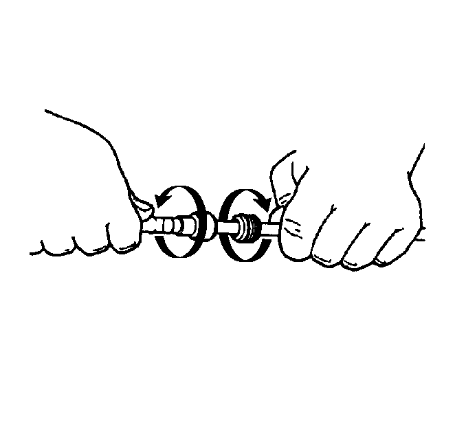
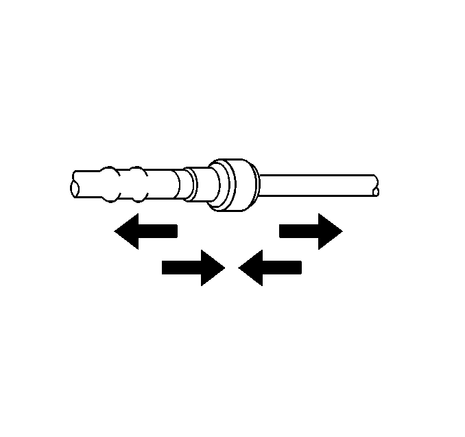
- Grasp both sides of the fitting. Twist the female connector ¼ turn in each direction in order to loosen any dirt within the fitting.
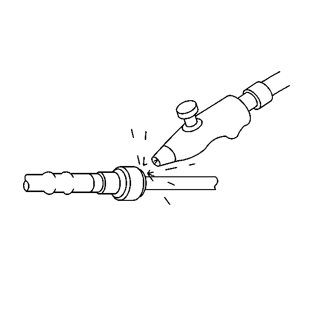
- Blow dirt out of the fitting using compressed air.
- Remove the connector locking assembly at the fuel rail.
- Choose the correct tool from J 37088-A tool set for the size of the fitting. Insert the tool into the female connector, then push inward in order to release the locking tabs.
- Pull the connection apart.
- Using a clean shop towel, wipe off the male pipe end.
- Inspect both ends of the fitting for dirt and burrs. Clean or replace the components as required.
Caution: Wear safety glasses when using compressed air in order to prevent eye injury.
Caution: Remove the fuel tank cap and relieve the fuel system pressure before servicing the fuel system in order to reduce the risk of personal injury. After you relieve the fuel system pressure, a small amount of fuel may be released when servicing the fuel lines, the fuel injection pump, or the connections. In order to reduce the risk of personal injury, cover the fuel system components with a shop towel before disconnection. This will catch any fuel that may leak out. Place the towel in an approved container when the disconnection is complete.
Notice: Cap the fittings and plug the holes when servicing the fuel system in order to prevent dirt and other contaminants from entering the open pipes and passages.
Important: Always maintain cleanliness when servicing fuel system components.


Notice: If necessary, remove rust or burrs from the fuel pipes with an emery cloth. Use a radial motion with the fuel pipe end in order to prevent damage to the O-ring sealing surface. Use a clean shop towel in order to wipe off the male tube ends. Inspect all the connections for dirt and burrs. Clean or replace the components and assemblies as required.
Installation Procedure
- Apply a few drops of clean engine oil to the male pipe end.
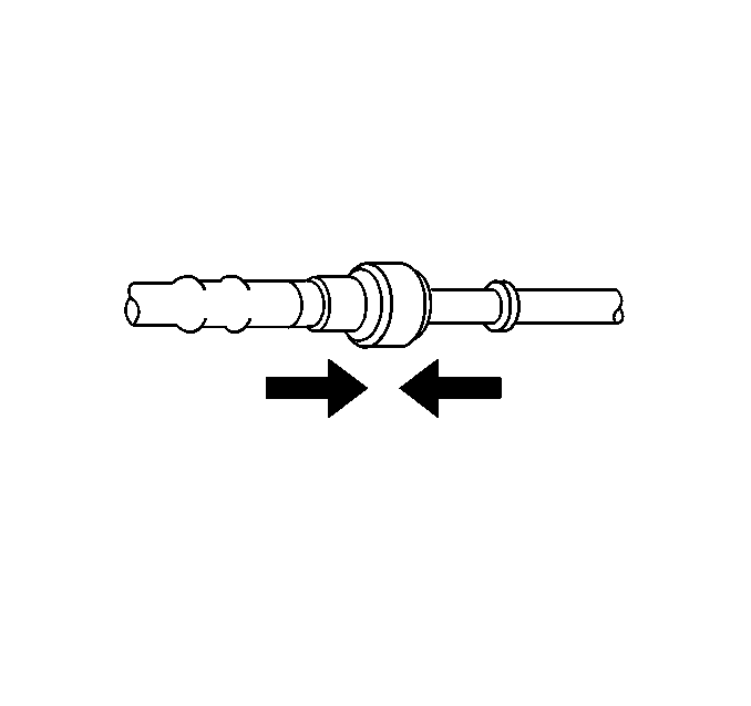
- Push both sides of the fitting together in order to cause the retaining tabs to snap into place.
- Once installed, pull on both sides of the fitting to ensure that the connection is secure.
- Install the connector locking assembly.
- Tighten the fuel filler cap.
- Connect the negative battery cable. Refer to Battery Negative Cable Disconnection and Connection in Engine Electrical.
- Inspect the fuel system for leaks by performing the following steps:
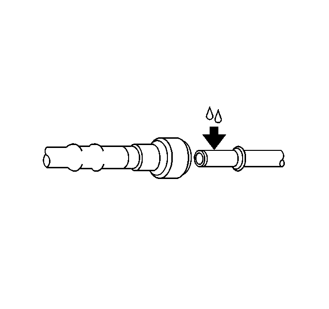
Caution: Always apply a few drops of clean engine oil to the male pipe ends before connecting the fuel pipe fittings in order to reduce the risk of fire and personal injury. This will ensure proper reconnection and prevent a possible fuel leak. During normal operation, the O-rings located in the female connector will swell and may prevent proper reconnection if not lubricated.
| 7.1. | Turn ON the ignition for 2 seconds. |
| 7.2. | Turn OFF the ignition for 10 seconds. |
| 7.3. | Turn ON the ignition. |
| 7.4. | Inspect for fuel leaks. |
