GM Service Manual Online
For 1990-2009 cars only
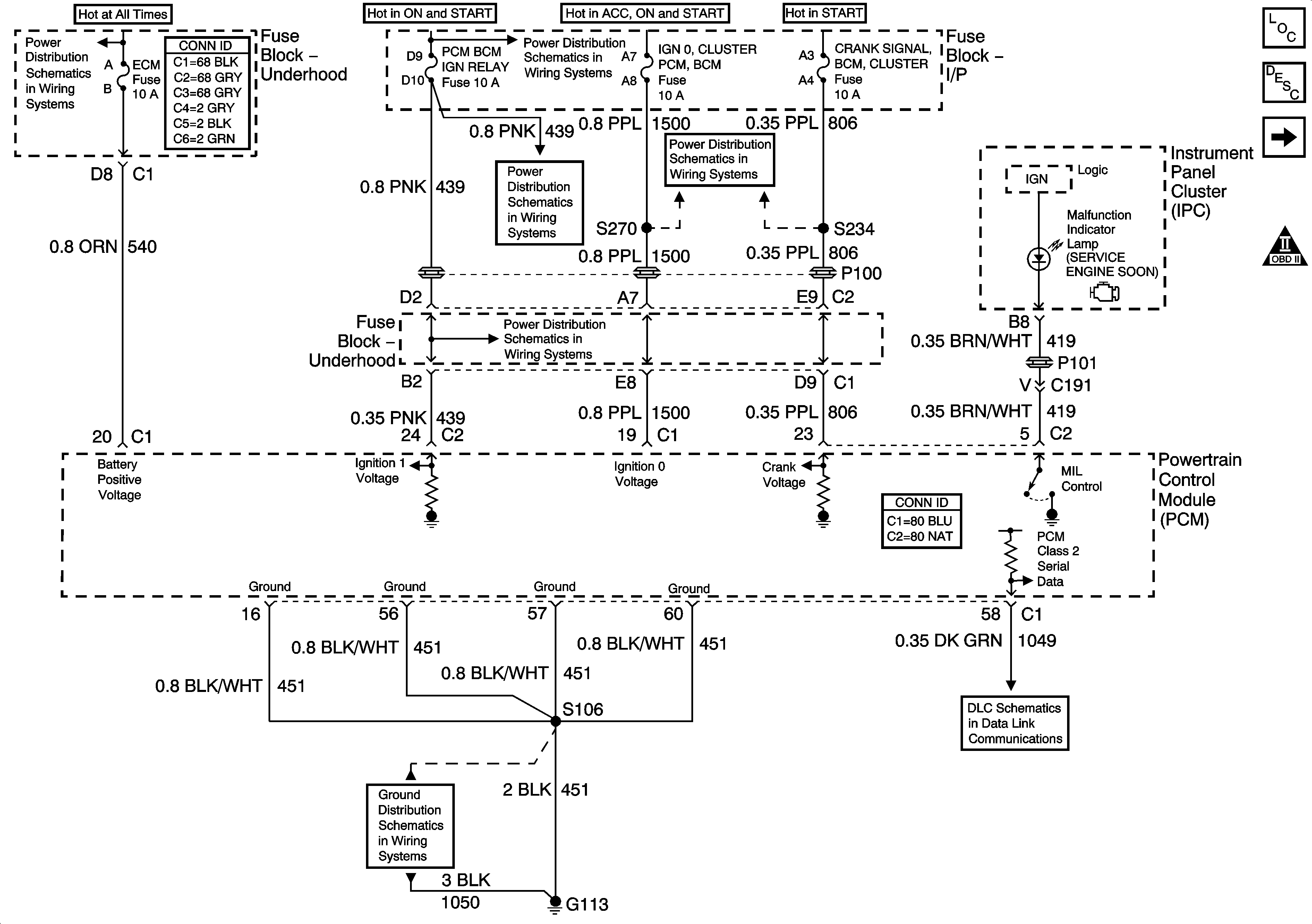
Figure 1:

Power, Ground, MIL, and Serial Data


Object Number: 789769  Size: FS
Master Electrical Component List
Powertrain Control Module Description
5 Volt, and Low Reference Bussing
Engine Controls Schematic Icons
R/CMPT RELEASE, ECM, GEN, HDLPL, and HDLPR Fuses
BTSI, TURN SIGNALS/CORN LPS, AIR BAG, CLUSTER, and PCM/BCM/U H RELAY Fuses
IGN 0 CLUSTER/PCM/BCM, and CRANK SIGNAL/BCM/CLUSTER Fuses
BTSI, TURN SIGNALS/CORN LPS, AIR BAG, CLUSTER, and PCM/BCM/U H RELAY Fuses
G113
DLC, and Splice Pack
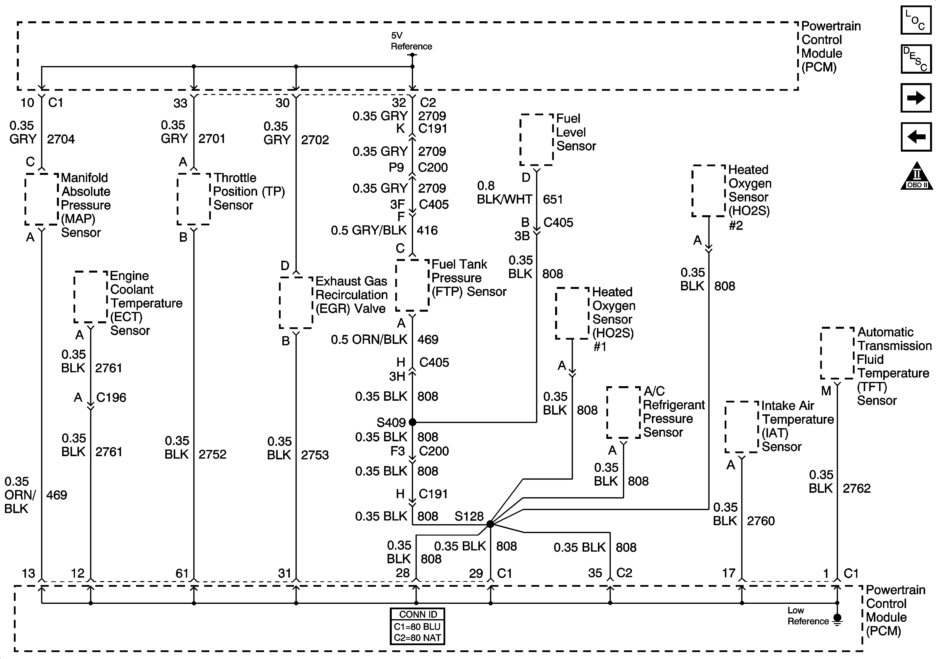
Figure 2:

5 Volt, and Low Reference Bussing


Object Number: 789770  Size: FS
Master Electrical Component List
Electronic Ignition (EI) System Description
TP, MAP, ECT, and IAT Sensors
Power, Ground, MIL, and Serial Data
Engine Controls Schematic Icons
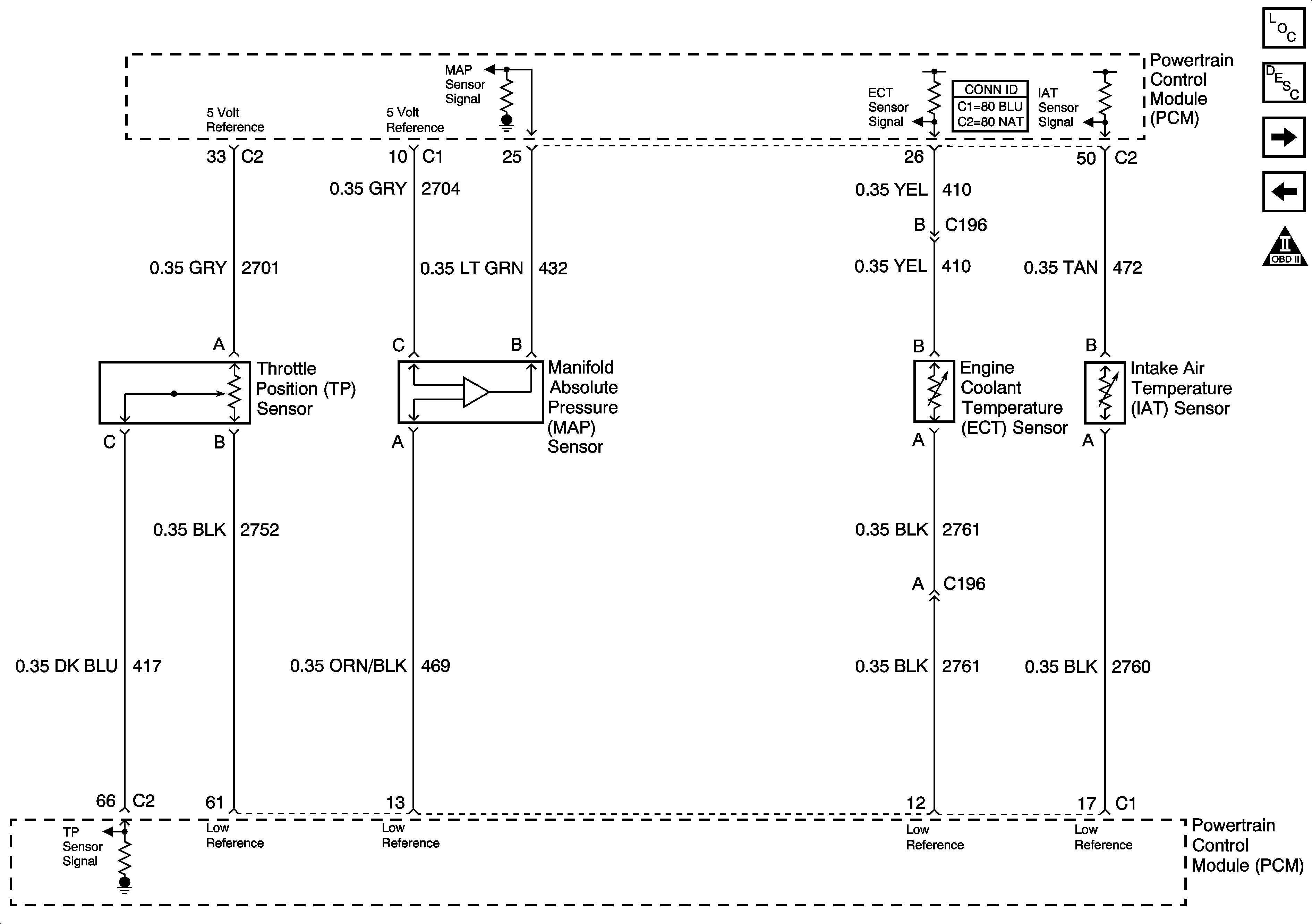
Figure 3:

TP, MAP, ECT, and IAT Sensors


Object Number: 789772  Size: FS
Master Electrical Component List
Electronic Ignition (EI) System Description
MAF, and VSS Circuits
5 Volt, and Low Reference Bussing
Engine Controls Schematic Icons
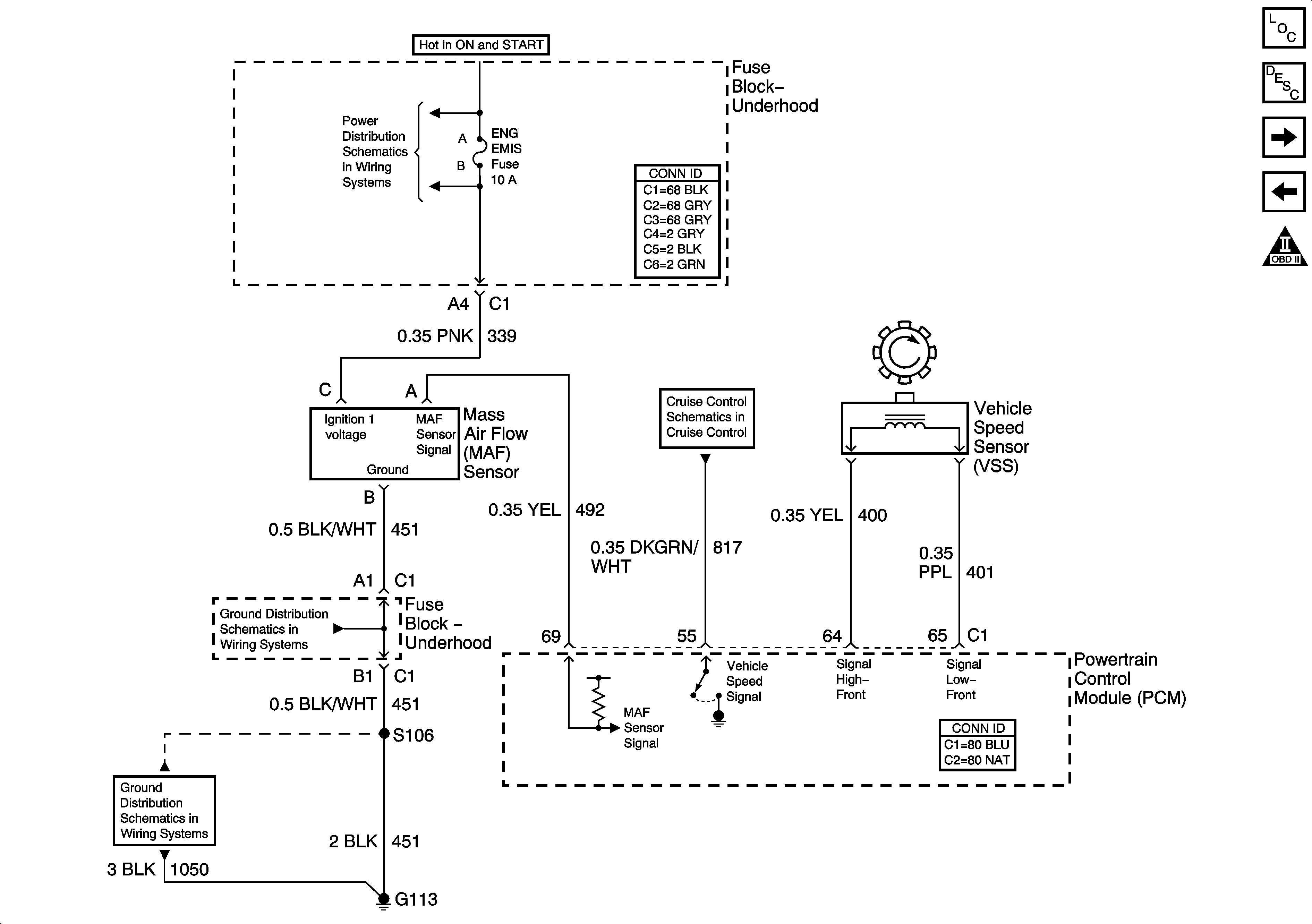
Figure 4:

MAF, and VSS Circuits


Object Number: 789773  Size: FS
Master Electrical Component List
Electronic Ignition (EI) System Description
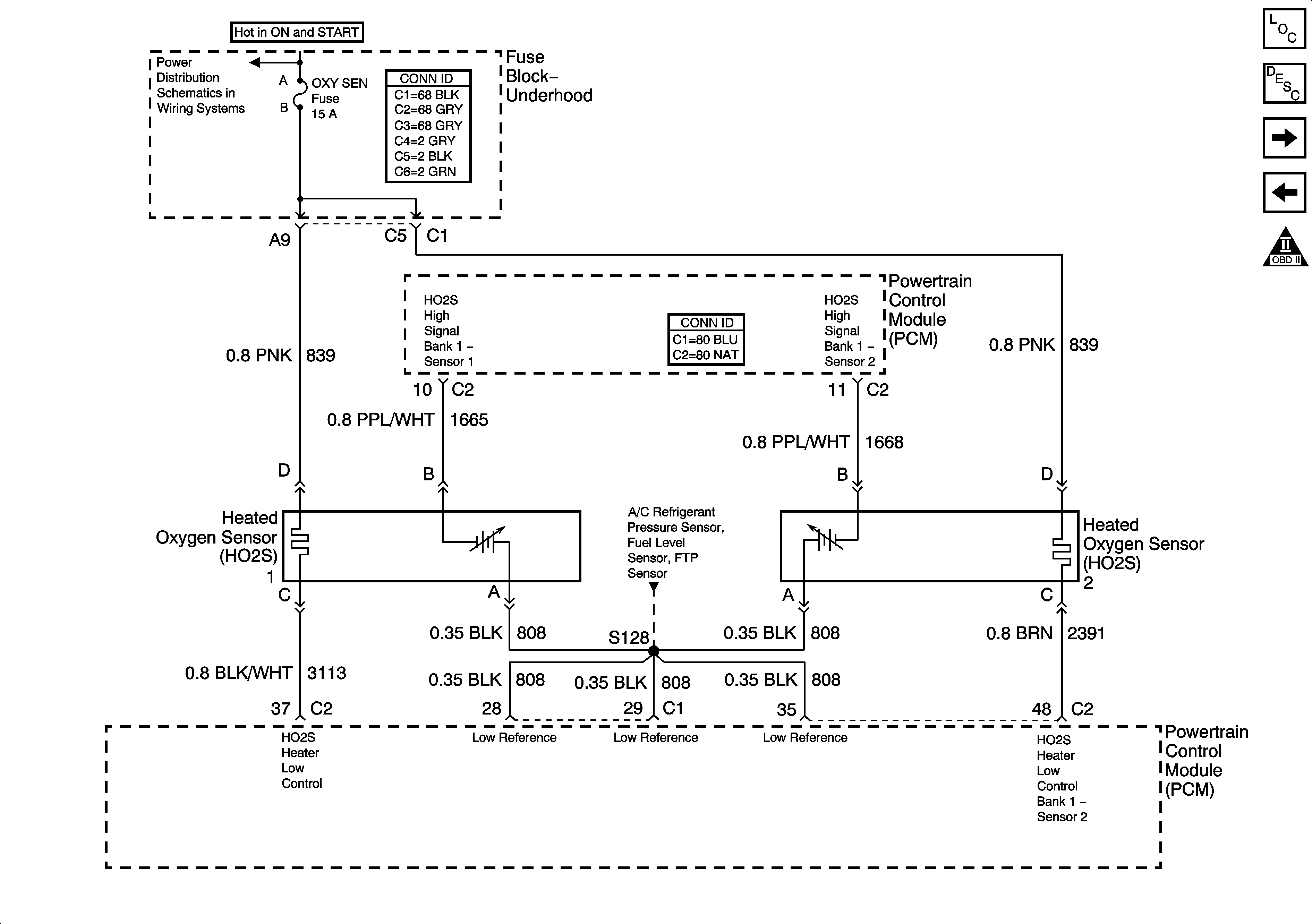
Heated Oxygen Sensors
TP, MAP, ECT, and IAT Sensors
Engine Controls Schematic Icons
A/C COMPRESSOR CLUTCH, IGN MAIN, COOLING FAN 1, COOLING FAN 2, and COOLING FAN 3 Relays, COOL FAN 1, and COOL FAN 2, Fuses,
PCM Serial Data
G113
G113
Figure 5:

Heated Oxygen Sensors


Object Number: 789774  Size: FS
Master Electrical Component List
Secondary Air Injection System Description
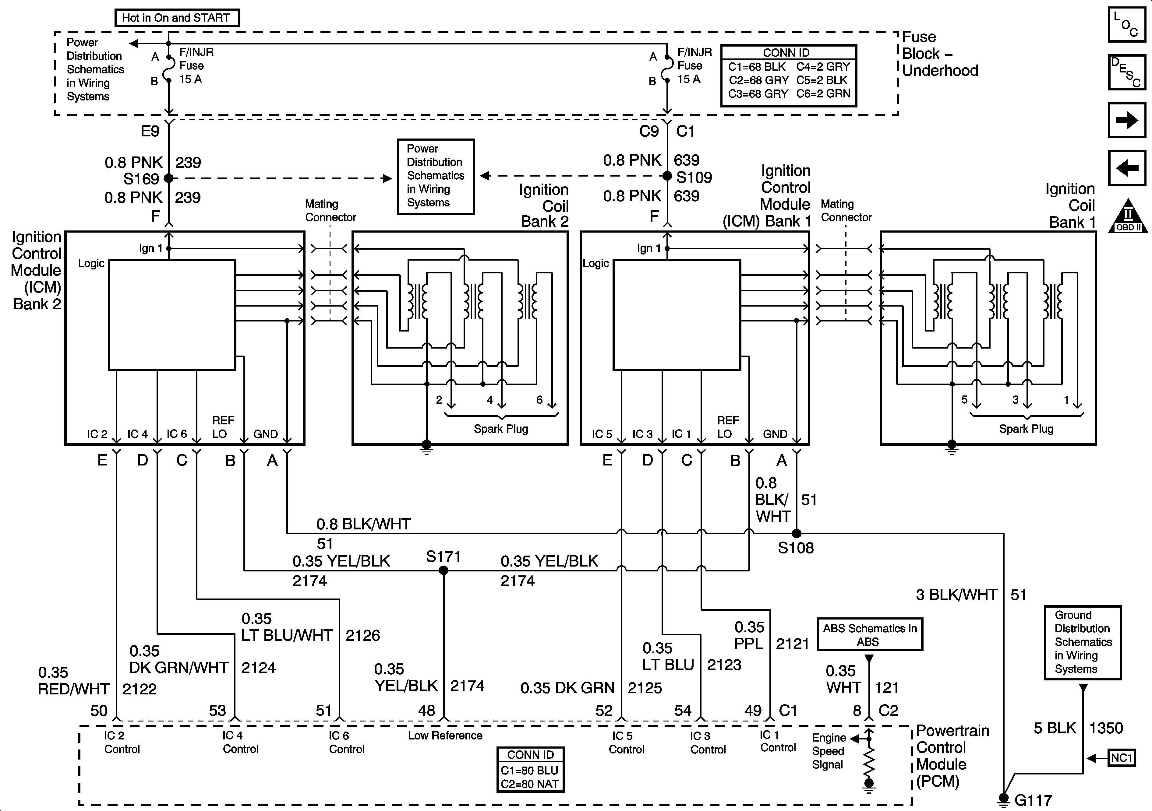
Ignition Coil, and Ignition Control Module
MAF, and VSS Circuits
Engine Controls Schematic Icons
TRANS, ABS, and OXY SEN Fuses
Figure 6:

Ignition Coil, and Ignition Control Module


Object Number: 789776  Size: FS
Master Electrical Component List
Electronic Ignition (EI) System Description
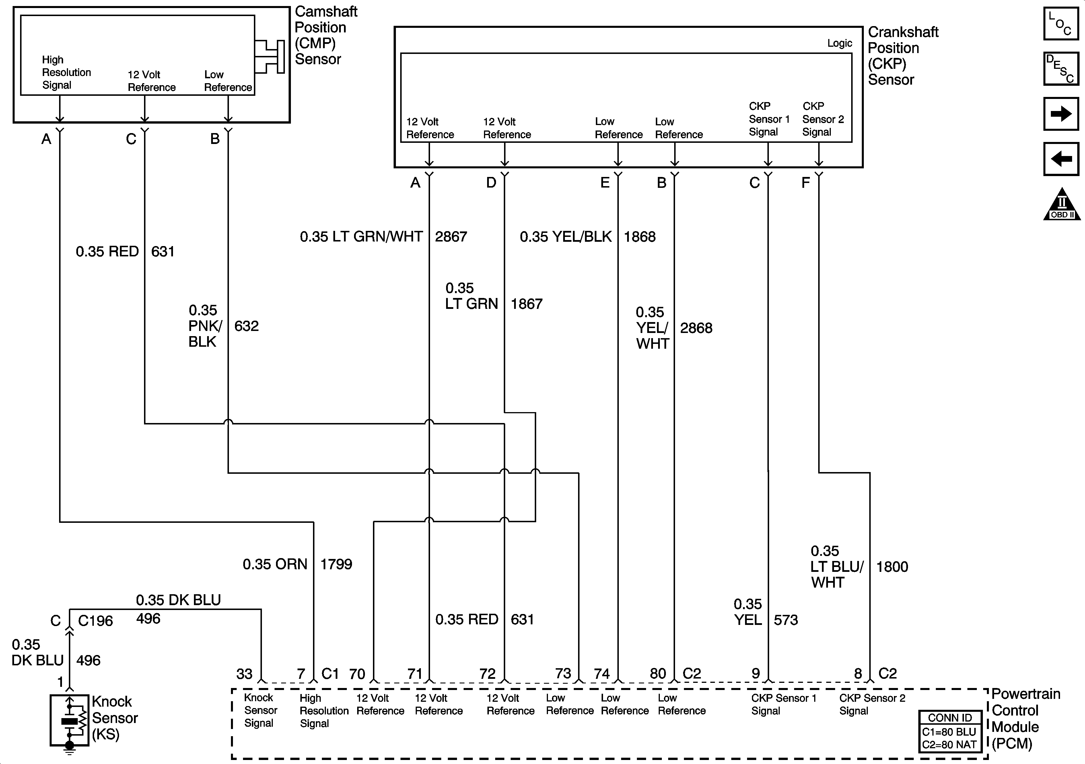
CMP, CKP, and Knock Sensors
Heated Oxygen Sensors
Engine Controls Schematic Icons
F/INJR Fuses
F/INJR Fuses
YAW and Lateral, Brake Pressure, and Steering Angle Sensors
G113, G117, G119)
Figure 7:

CMP, CKP, and Knock Sensors


Object Number: 789779  Size: FS
Master Electrical Component List
Electronic Ignition (EI) System Description
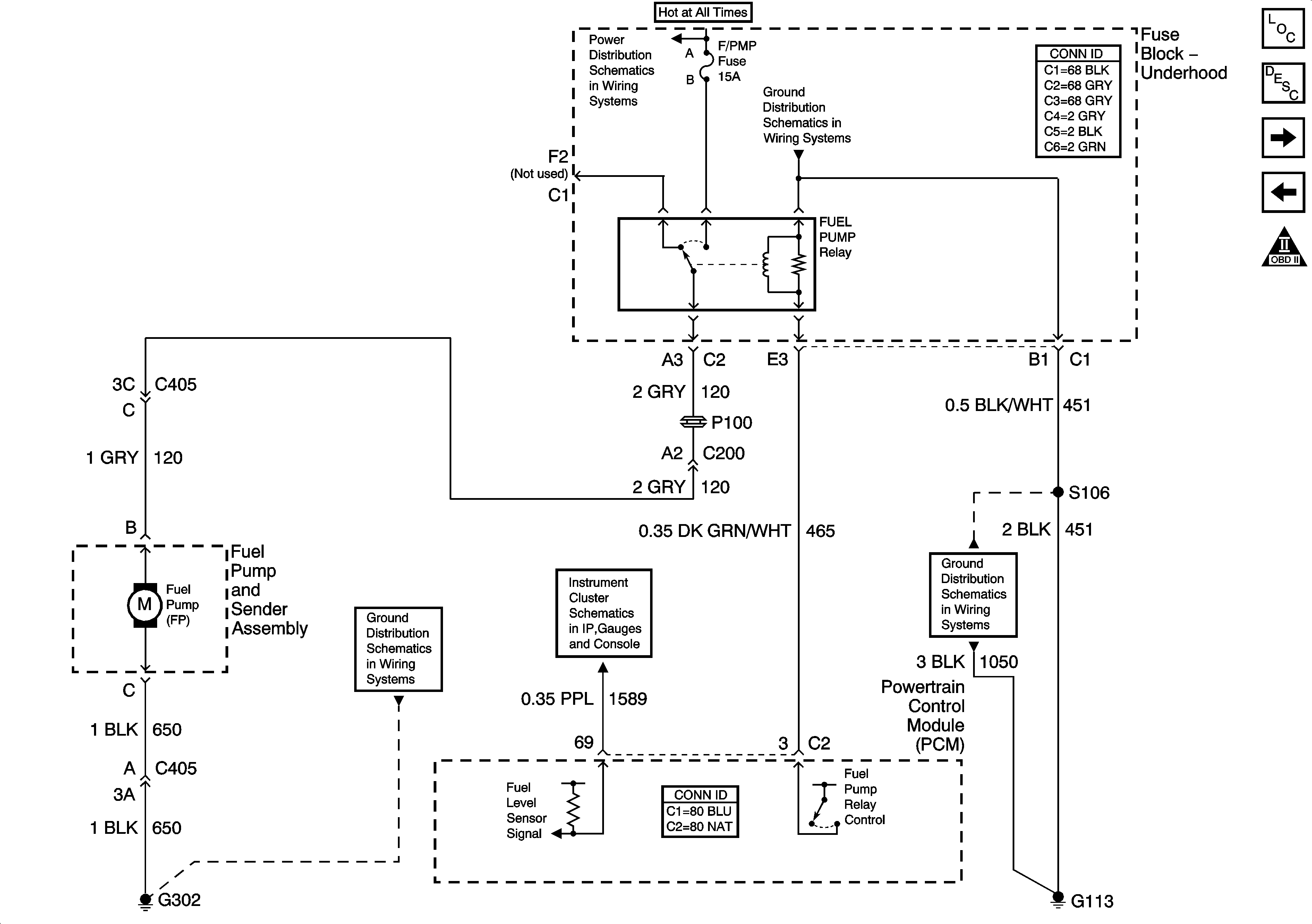
Fuel Pump Relay, and Fuel Pump
Ignition Coil, and Ignition Control Module
Engine Controls Schematic Icons
Figure 8:

Fuel Pump Relay, and Fuel Pump


Object Number: 789786  Size: FS
Master Electrical Component List
Fuel System Description
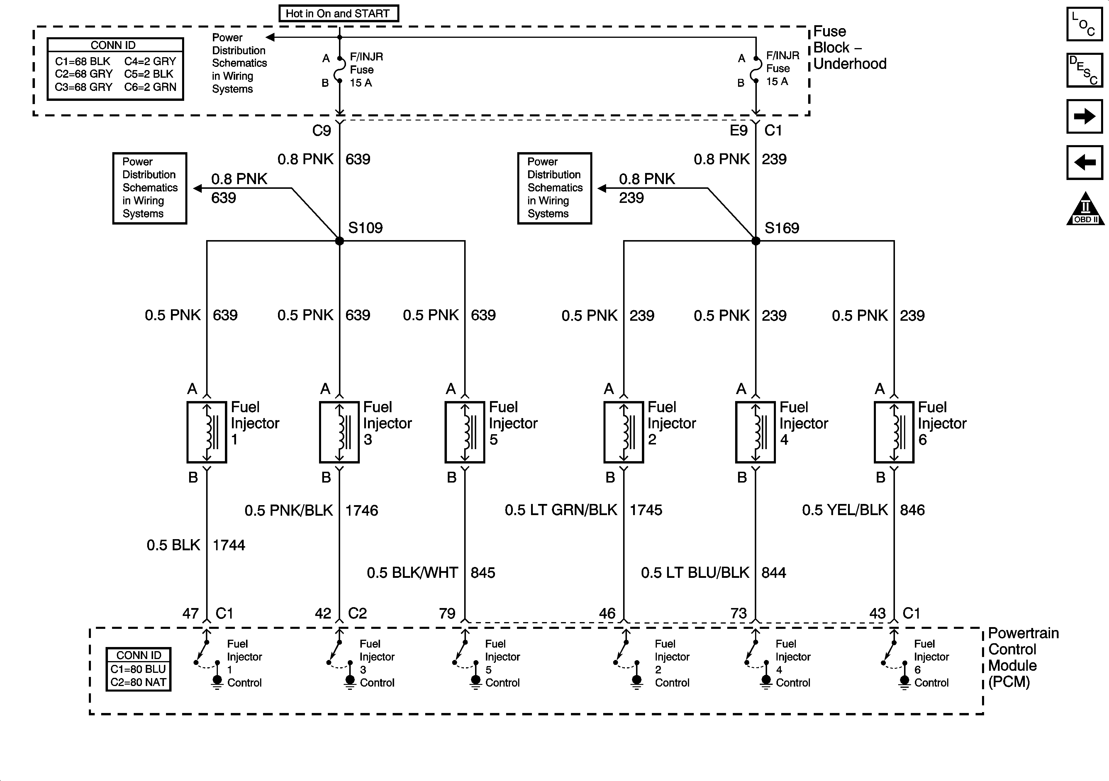
Fuel Injectors
CMP, CKP, and Knock Sensors
Engine Controls Schematic Icons
Fuse Block-Underhood Bussing (1 of 2)
G113
G302
Gages
G113
Figure 9:

Fuel Injectors


Object Number: 789788  Size: FS
Master Electrical Component List
Fuel System Description
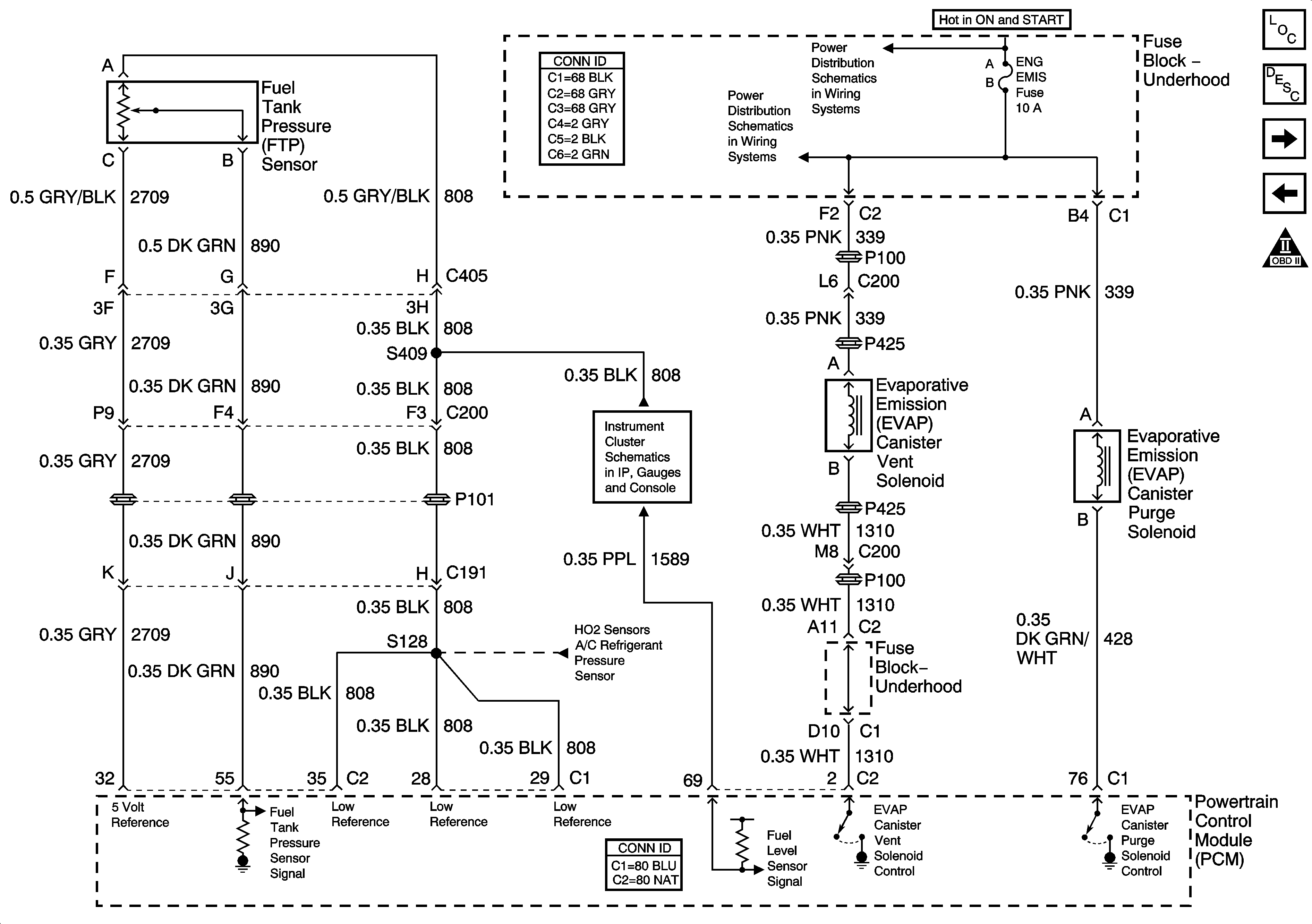
FTP, and EVAP Solenoids
Fuel Pump Relay, and Fuel Pump
Engine Controls Schematic Icons
F/INJR Fuses
F/INJR Fuses
F/INJR Fuses
Figure 10:

FTP, and EVAP Solenoids


Object Number: 789789  Size: FS
Master Electrical Component List
Evaporative Emission Control System Description
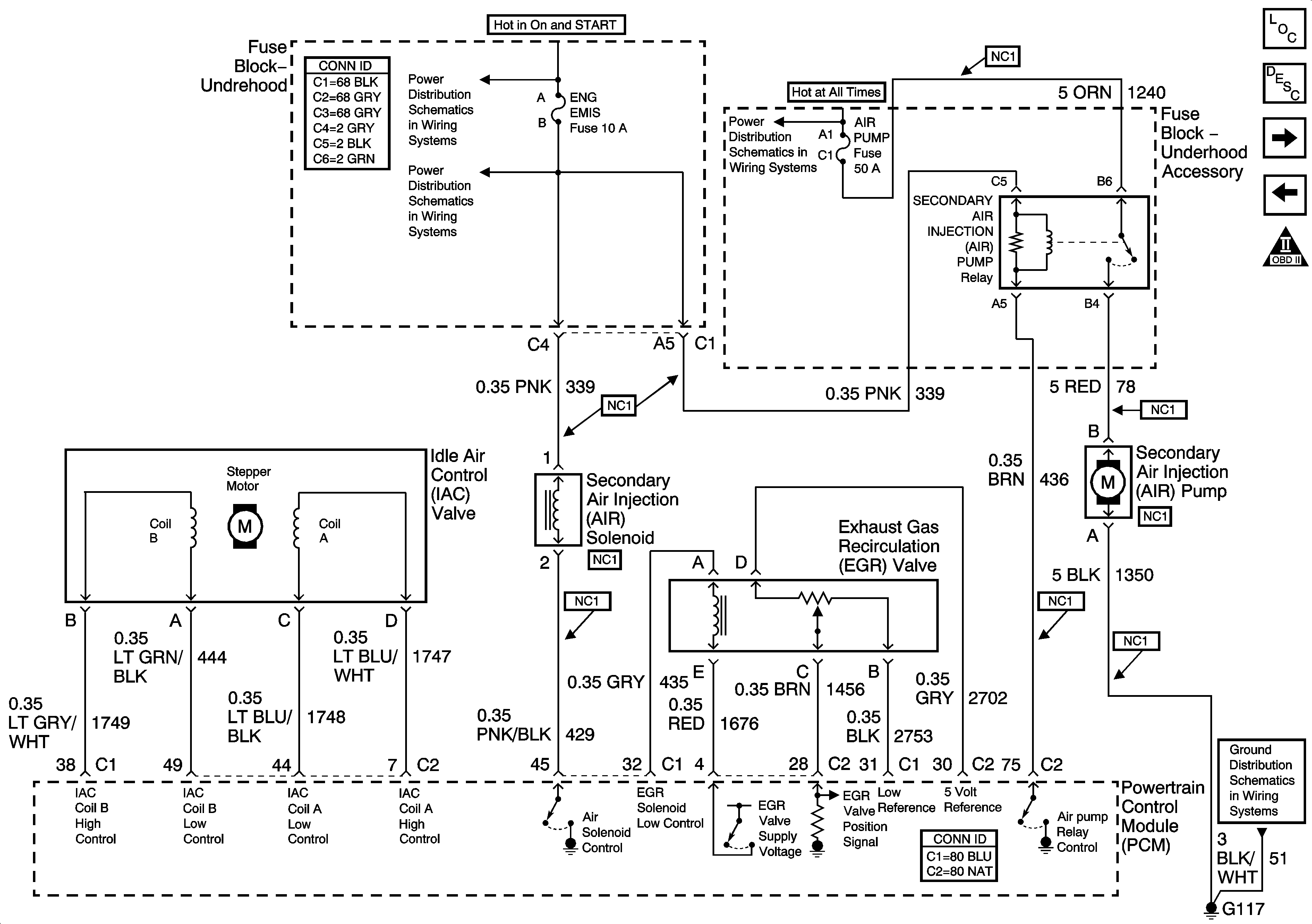
IAC, AIR Solenoid, EGR, and AIR Pump
Fuel Injectors
Engine Controls Schematic Icons
A/C COMPRESSOR CLUTCH, IGN MAIN, COOLING FAN 1, COOLING FAN 2, and COOLING FAN 3 Relays, COOL FAN 1, and COOL FAN 2, Fuses,
Gages
Figure 11:

IAC, AIR Solenoid, EGR, and AIR Pump


Object Number: 789790  Size: FS
Master Electrical Component List
Secondary Air Injection System Description
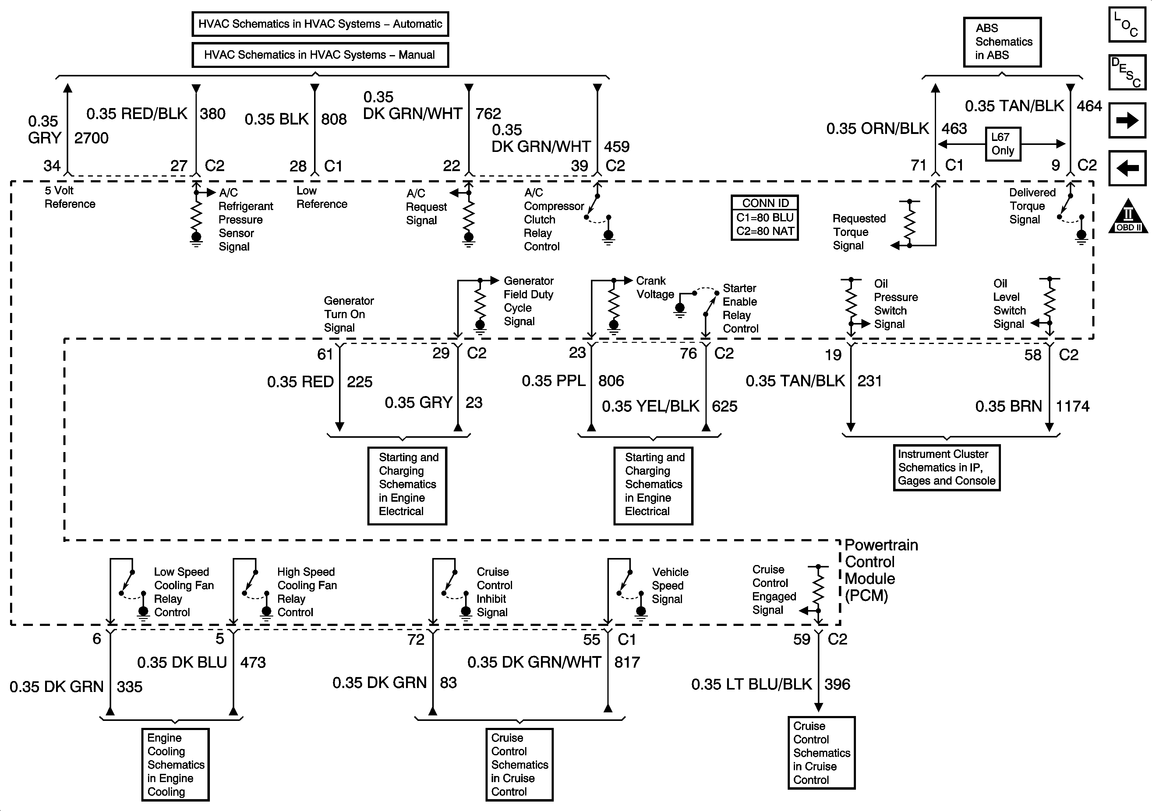
HVAC, ABS, Cruise Control, Starter, and Generator Circuits
FTP, and EVAP Solenoids
Engine Controls Schematic Icons
A/C COMPRESSOR CLUTCH, IGN MAIN, COOLING FAN 1, COOLING FAN 2, and COOLING FAN 3 Relays, COOL FAN 1, and COOL FAN 2, Fuses,
Fuse Block-Underhood Accessory
G113, G117, G119)
Figure 12:

HVAC, ABS, Cruise Control, Starter, and Generator Circuits


Object Number: 789791  Size: FS
Master Electrical Component List
Powertrain Control Module Description
PNP, and Stop Lamp Circuits
IAC, AIR Solenoid, EGR, and AIR Pump
Engine Controls Schematic Icons
Compressor Controls
Power, Grounds, and Blower Controls
ABS Indicator, Torque Signals, and Traction Control Switch
Generator, and Charging Indicator Circuits
Power, Grounds, Ignition Sw, and Starter Circuits
Engine and Security Indicators
Power, Ground, Cooling Fans, Relays, and Level Switch
PCM Serial Data
PCM Serial Data
Figure 13:

PNP, and Stop Lamp Circuits


Object Number: 789792  Size: FS
Master Electrical Component List
Powertrain Control Module Description
HVAC, ABS, Cruise Control, Starter, and Generator Circuits
Engine Controls Schematic Icons
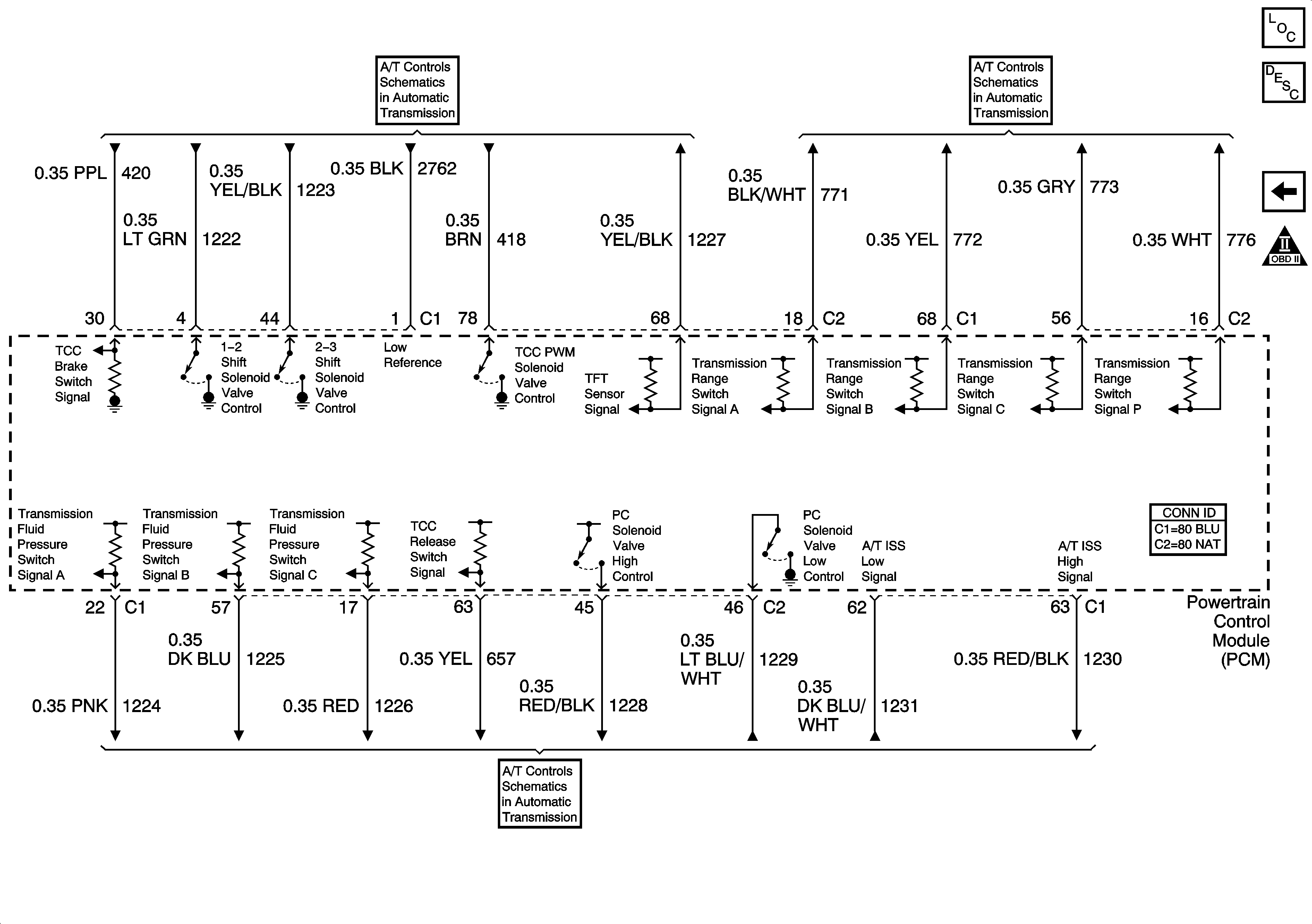
VSS, and TCC
PNP Switch
SS, Pressure Control Solenoid, Pressure Switch