Tools Required
J 38185 Hose Clamp Pliers
Removal Procedure
- Drain the cooling system. Refer to Cooling System Draining and Filling in Engine Cooling.
- UseJ 38185 in order to position aside the heater hose inlet and outlet clamp from the heater core.
- Disconnect the inlet and outlet heater hose from the heater core.
- Cap off the heater core pipes.
- Remove the IP trim pad. Refer to Instrument Panel Trim Pad Replacement in Instrument Panel, Gages and Console.
- Remove the screws from the heater core outlet cover.
- Remove the heater core outlet cover.
- Remove the screws from the heater core cover.
- Remove the heater core cover.
- Remove and discard the seals (1,2,3) from the heater core cover.
- Remove and discard the heater core outer seal (5) from the heater core.
- Remove the heater core clamp screw (1).
- Remove the heater core retaining clamp.
- Remove the pipe retainer clamp screw (2) from the heater core.
- Remove the heater core from the lower case of the HVAC module assembly.
- Remove and discard the lower seal (4) from the HVAC module assembly case.
- Remove and discard the center seal (3) from the HVAC module assembly case.
- Remove and discard the upper seal (2) from the HVAC module assembly lower case.
- Remove and discard the side seals (1) from the HVAC module assembly lower case.

Important: Cap off the pipes in order to prevent coolant spillage inside the vehicle.

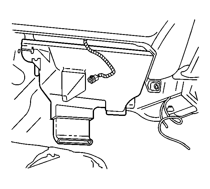
Important: Position the heater core cover downward and rearward in order to disconnect the cover from the rear area floor duct assembly.


Installation Procedure
- Install the side seals (1) to the HVAC module assembly lower case.
- Install the upper seal (2) to the HVAC module assembly lower case.
- Install the center seal (3) to the HVAC module assembly case.
- Install the lower seal (4) to the HVAC module assembly case.
- Install the heater core to the lower case of the HVAC module assembly.
- Install the screw (2) to the heater core line clamp.
- Install the screw (1) which secures the heater core mounting clip.
- Install heater core outer seal (5) to the heater core.
- Install new seals (1,2,3) to the heater core cover.
- Install the heater core cover.
- Install the screws which secure the heater core cover.
- Install the heater core outlet cover.
- Install the screws which secure the heater core outlet cover.
- Install the IP trim pad. Refer to Instrument Panel Trim Pad Replacement in Instrument Panel, Gages and Console.
- Connect the inlet and outlet heater hose to the heater core .
- UseJ 38185 in order to reposition the heater hose inlet and outlet clamp to the heatrer core.
- Filll the coolant. Refer to Cooling System Draining and Filling in Engine Cooling.


Notice: Use the correct fastener in the correct location. Replacement fasteners must be the correct part number for that application. Fasteners requiring replacement or fasteners requiring the use of thread locking compound or sealant are identified in the service procedure. Do not use paints, lubricants, or corrosion inhibitors on fasteners or fastener joint surfaces unless specified. These coatings affect fastener torque and joint clamping force and may damage the fastener. Use the correct tightening sequence and specifications when installing fasteners in order to avoid damage to parts and systems.
Tighten
Tighten the screw to 1.5 N·m (13 lb in).
Tighten
Tighten the screw to 1.5 N·m (13 lb in).


Tighten
Tighten the screws to 1.5 N·m (13 lb in).

Tighten
Tighten the screws to 1.5 N·m (13 lb in).

Important: Position the heater hose clamps in the indicated location
