Tools Required
| • | J 39400-A Halogen Leak Detector |
| • | J 38185 Hose Clamp Pliers |
Removal Procedure
- Recover the refrigerant. Refer to Refrigerant Recovery and Recharging .
- Drain the cooling system. Refer to Cooling System Draining and Filling in Engine Cooling.
- Remove the left sheet metal diagonal brace. Refer to Front End Sheet Metal Diagonal Brace Replacement in Body Front End.
- Remove the accumulator tube to evaporator core block fitting bolt.
- Disconnect the accumulator tube from the evaporator.
- Disconnect the evaporator tube from the evaporator.
- UseJ 38185 in order to position aside the heater hose inlet and outlet clamp from the heater core.
- Disconnect the inlet and outlet heater hose from the heater core.
- Cap off the heater core pipes.
- Remove the instrument panel trim pad. Refer to Instrument Panel Trim Pad Replacement in Instrument Panel, Gages, and Controls.
- Remove the passenger SIR inflator module. Refer to Inflatable Restraint Instrument Panel Module Replacement in SIR.
- Remove the screws from the right and left side air distributor duct.
- Remove the right and left side air distributor duct.
- Remove the brake pedal. Refer to Brake Pedal Replacement in Hydraulic Brakes.
- Remove the bolts from the steering column support bracket and remove the bracket.
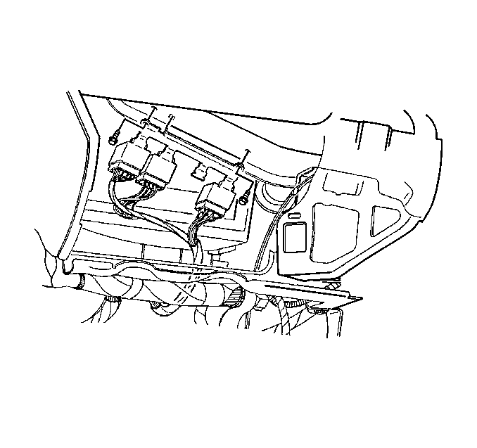
- Remove the bolts retaining the relay bracket and reposition the bracket.
- Remove the bolts retaining the BCM bracket and reposition the BCM bracket aside.
- Remove the bolts which secure the center support bracket of the HVAC module.
- Remove the center support bracket of the HVAC module.
- Release the wiring harness retaining clips from the cross vehicle beam and position the wiring harness aside.
- Remove the two screws below the fuse block that hold the main wire harness connector to the cross vehicle beam.
- Remove the bolts which retain the HVAC module to the cross vehicle beam.
- Remove the bolts which retain the cross vehicle beam to the left hinge pillar.
- Remove the bolts which retain the cross vehicle beam to the right hinge pillar.
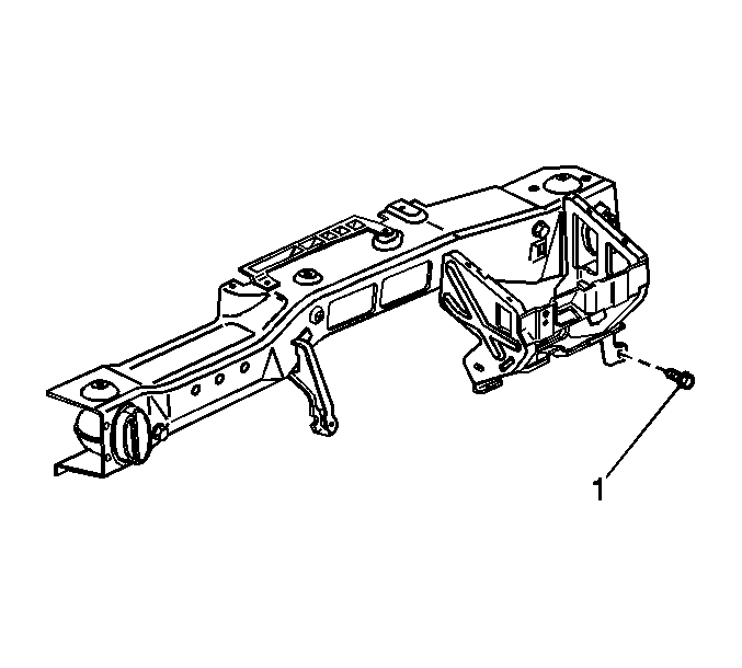
- Remove the bolt (1) from the cross vehicle beam.
- Remove the cross vehicle beam from the vehicle.
- Remove the screws from the heater core outlet cover.
- Remove the heater core outlet cover.
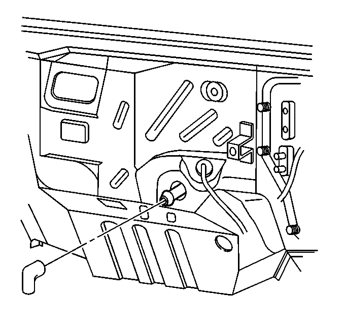
- Remove the evaporator drain elbow.
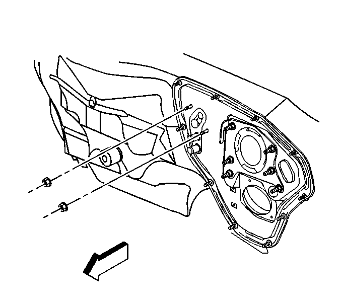
- Remove the nuts which secure the HVAC module assembly to the dash.
- Disconnect the vacuum hoses from the HVAC module assembly.
- Disconnect the electrical connectors from the HVAC module assembly.
- Remove the HVAC module assembly.
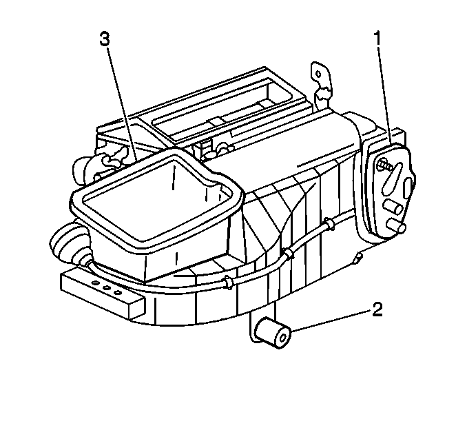
- Remove the outer HVAC module assembly seals (1,2,3).
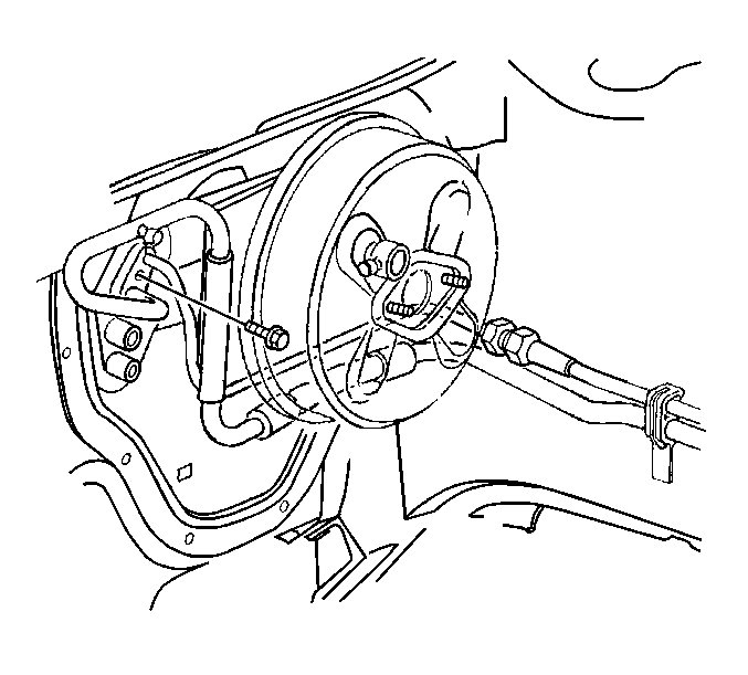

Important: Cap off the pipes in order to prevent coolant spillage inside the vehicle.
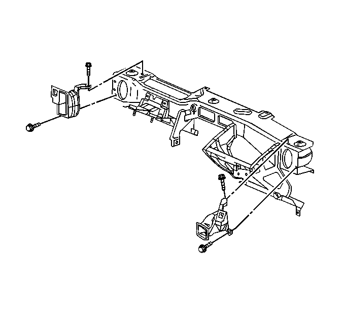
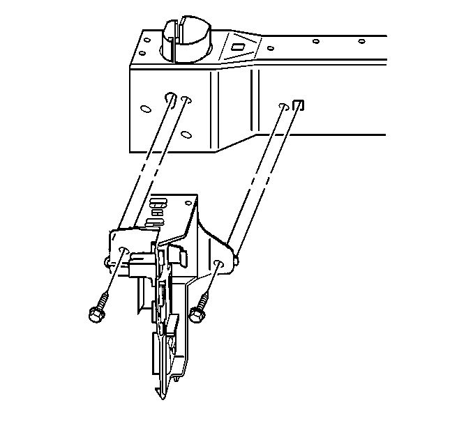
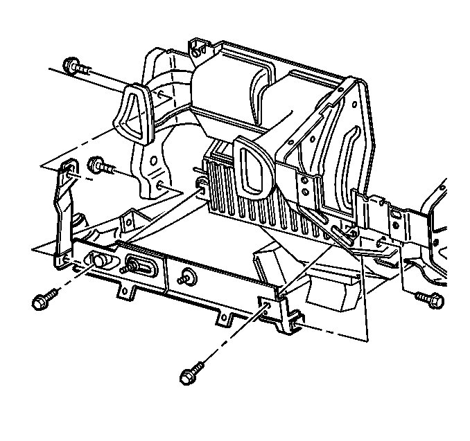
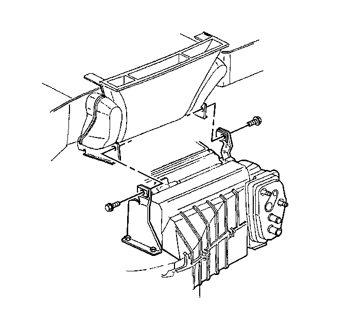
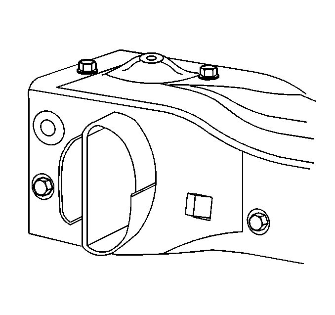
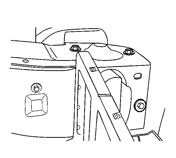
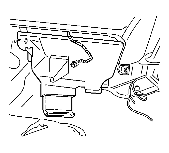
Important: Position the heater core cover downward and rearward in order to disconnect the cover from the rear area floor duct assembly.
Installation Procedure
- Install new outer HVAC module assembly seals (1,2,3).
- Install the HVAC module assembly to the vehicle.
- Install the nuts which secure the HVAC module assembly to the dash.
- Install the evaporator drain elbow.
- Connect the electrical connectors to the HVAC module assembly.
- Connect the vacuum hoses to the HVAC module assembly.
- Install the cross vehicle beam to the vehicle.
- Install the cross vehicle beam to the right hinge pillar with the retaining bolts, but do NOT tighten.
- Install the cross vehicle beam to the left hinge pillar with the retaining bolts.
- Tighten the bolts retaining the cross vehicle beam to both the left and the right hinge pillars.
- Install the HVAC module to the cross vehicle beam with the retaining bolts.
- Install the bolt (1) to the cross vehicle beam.
- Install the center support bracket to the HVAC module.
- Secure the module to the bracket with the retaining bolts.
- Install the instrument panel wiring harness on to the cross vehicle beam and secure the retaining clips.
- Install the two screws below the fuse block that hold the main wire harness connector to the cross vehicle beam.
- Install the BCM bracket into position.
- Install the BCM bracket retaining bolts.
- Install the relay bracket into position.
- Install the relay bracket retaining bolts.
- Install the support bracket and bolts for the steering column.
- Install the brake pedal. Refer to Brake Pedal Replacement in Hydraulic Brakes.
- Install the right and left side air distributor duct.
- Install the screws to the right and left side air distributor duct.
- Install the passenger SIR inflator module. Refer to Inflatable Restraint Instrument Panel Module Replacement in SIR.
- Install the instrument panel trim pad. Refer to Instrument Panel Trim Pad Replacement in Instrument Panel, Gages, and Controls.
- Connect the inlet and outlet heater hose to the heater core.
- UseJ 38185 in order to reposition the heater hose inlet and outlet clamps to the heater core.
- Replace the O-ring seals on the evaporator tube and the accumulator tube. Refer to O-Ring Replacement .
- Connect the evaporator tube to the evaporator.
- Connect the accumulator tube to the evaporator.
- Install the accumulator tube to evaporator core block fitting bolt.
- Refill the coolant. Refer to Cooling System Draining and Filling in Engine Cooling.
- Install the left sheet metal diagonal brace. Refer to Front End Sheet Metal Diagonal Brace Replacement in Body Front End.
- Evacuate and recharge the A/C system. Refer to Refrigerant Recovery and Recharging .
- Leak test the fittings of the component using J 39400-A .


Notice: Use the correct fastener in the correct location. Replacement fasteners must be the correct part number for that application. Fasteners requiring replacement or fasteners requiring the use of thread locking compound or sealant are identified in the service procedure. Do not use paints, lubricants, or corrosion inhibitors on fasteners or fastener joint surfaces unless specified. These coatings affect fastener torque and joint clamping force and may damage the fastener. Use the correct tightening sequence and specifications when installing fasteners in order to avoid damage to parts and systems.
Tighten
Tighten the nuts to 10 N·m (89 lb in).

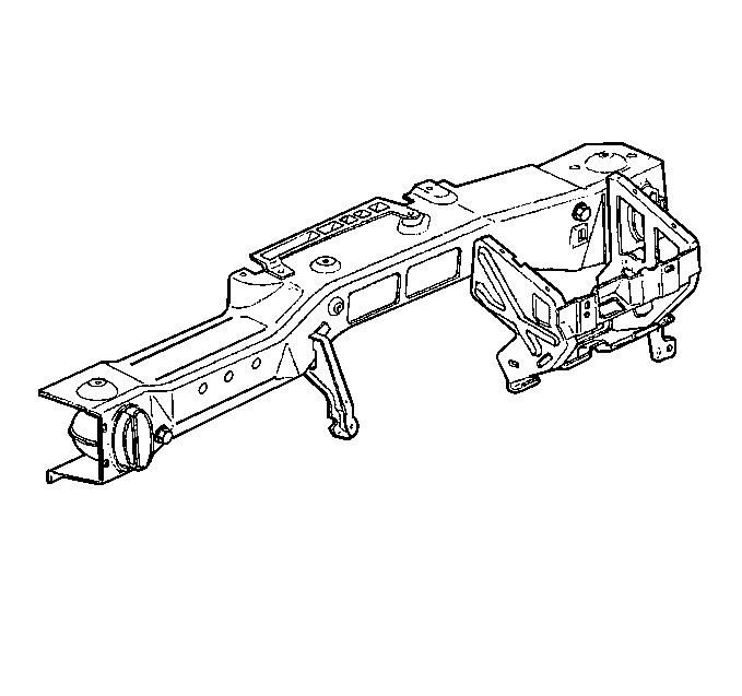

Important: Do not tighten bolts until you have installed all of the bolts.

Tighten
Tighten the bolts to 25 N·m (18 lb ft).

Tighten
Tighten the bolts to 10 N·m (89 lb in).

Tighten
Tighten the bolt to 20 N·m (15 lb ft).

Tighten
Tighten the retaining bolts to 10 N·m (89 lb in).

Tighten
Tighten the retaining bolts to 10 N·m (89 lb in).

Tighten
Tighten the retaining bolts to 10 N·m (89 lb in).
Tighten
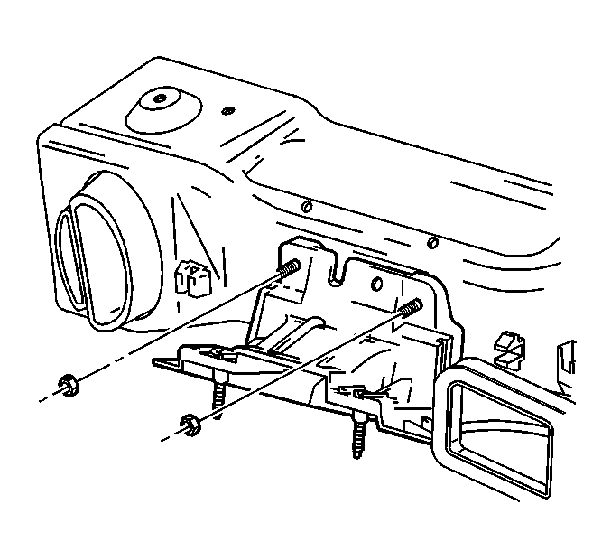
Tighten the reinforcement nuts to 50 N·m (37 lb ft).

Tighten
Tighten the screws to 1.5 N·m (13 lb in).

Important: Position the heater hose clamps in the indicated location.

Tighten
Tighten the bolt to 16 N·m (12 lb ft).
