EXCESSIVE FUEL PUMP NOISE REPAIR PROCEDURES

VEHICLES AFFECTED: Some 1985 and 1986 'C' and 1986 'H' Models with 3.8L Port Fuel Injected Engines (VIN Codes 3 or B)
Some 1985 and 1986 'C' and 1986 'H' Models equipped with 3.8L Port Fuel Injected Engines (VIN Codes 3 or B) may experience an excessive fuel pump noise condition.
In most cases, this noise is transmitted from interference between the fuel lines, fuel tank, and underbody. The following instructions may be used to isolate the fuel tank and lines from one another and the vehicle underbody.
Parts Required:
(1) 22530899 - Sound Isolation Kit (2) 6472359 - Pulsator (3) 22515965 - Fuel Sender O-Ring (4) 3899696 - 7/16" Flat Washers or Equivalent
NOTE: When replacing the pulsator, observe the fuel pump part number located on the pump housing under the foam rubber cover. If the pump number is 6442439, 6442435, 6442410, or 6442409, the fuel pump should also be replaced with the latest design as catalogued by GM Parts Department.
Isolation Instructions:
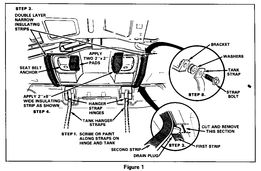
1. Using a fast drying spray paint or a scribe, mark the fuel tank hanger strap location across the bottom of the tank and hanger strap hinge location. This will be needed for reinstallation (See Figure 1).
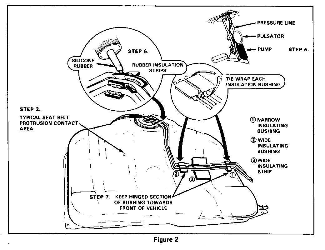
2. After draining fuel, lower tank and examine tank and tank cavity of underbody for interference. In some cases, the tank may ground out on the passenger side seat belt anchor protrusion. This will be apparent by a depression or shiny spot on the tank (See Figure 2).
3. Normally, the two long narrow insulating strips will adhere to the top of the fuel tank cavity of the underbody. If they are loose or not centrally positioned, resecure with adhesive, and cut off that section of each strip that lays across each body drain plug (See Figure 1).
NOTE: Some early 1985 Electras may have soft compressible white or hard asbestos type insulation strips. If this is the case, remove them and use two additional 1" x 24" strips from a second kit.
Then lay a second new 1" x 24" insulator strip from the kit part, Part Number 22530899, over each of the original ones so as to double strip each cavity insulator strip, without cutting off the area over the drain plug (See Figure 1).
4. Remove the pads from both seat belt anchor protrusions and reinstall the 2" x 6" pad on the right seat belt anchor protrusion and the 2" x 2" along with one new 2" x 2" from the kit on the left seat belt protrusion. Secure pads in place with duct tape (See Figure 1).
5. Remove fuel pump and sender assembly and replace pulsator, Part Number 6472359. Inspect pump part number as described previously and replace as necessary. Check that the pump is not bottoming out on the tank bottom by removing the O-Ring and reinstalling the pump and sender assembly in the tank and noticing if sender cover rests on the O-Ring seat. If the sender cover does not rest on the O-Ring seat of the tank, the pump might be bottomed out on the tank bottom. Repair as necessary. Install new fuel sender O-Ring, (Part Number 22515965) and reinstall fuel pump and sender assembly in tank (See Figure 2).
6. Examine steel sender lines at bend near the tank opening. They must not contact one another or the fuel tank. If possible, separate the tubes, taking care not to damage or deform tubes or break solder connection at sender cover. If required, cut rubber strips and fit them between and under the pipes to eliminate metal to metal contact. Prior to installing tank, apply silicone rubber sealer to rubber strips to permanently hold them in position (See Figure 2).
7. Position the new wide and narrow insulation bushings from the kit, as shown, making sure the hinged portion of the bushing is towards the front of the vehicle. Place the one wide insulator strip under the centre of the curved portion of the fuel lines. This wide insulator strip will not allow the pipes to contact the top of the fuel tank. Position the narrow insulator bushing close to the groove in the tank at the extreme driver's side of the fuel tank making sure all lines lay flat.
To assist in providing for positive positioning of the insulation bushings, place a small amount of silicone rubber in the grooves of each bushing. Then insert the tubes in the bushing. Tie wrap the assembly twice, locating the lock tabs to the side (See Figure 2).
8. If no interference was shown as discussed in Step #2, use the locator marks from Step #1 to reinstall tank in the same exact location from which it was removed. If interference was shown, shift the tank to the driver's side 1/4 inch before securing strap bolts. Place two 7/16 flat washers (Part Number 3899696) or equivalent, on both strap bolts between the straps and anchor flange and tighten bolts to 25 ft. lbs. (34 N.m) (See Figure 1).
9. Check the fuel lines in the area of the fuel filter, outer edge of the tank on the driver's side, and emergency brake cables. Do not allow any metal to metal contact. Insulate with rubber pads and secure with silicone rubber.


General Motors bulletins are intended for use by professional technicians, not a "do-it-yourselfer". They are written to inform those technicians of conditions that may occur on some vehicles, or to provide information that could assist in the proper service of a vehicle. Properly trained technicians have the equipment, tools, safety instructions and know-how to do a job properly and safely. If a condition is described, do not assume that the bulletin applies to your vehicle, or that your vehicle will have that condition. See a General Motors dealer servicing your brand of General Motors vehicle for information on whether your vehicle may benefit from the information.
