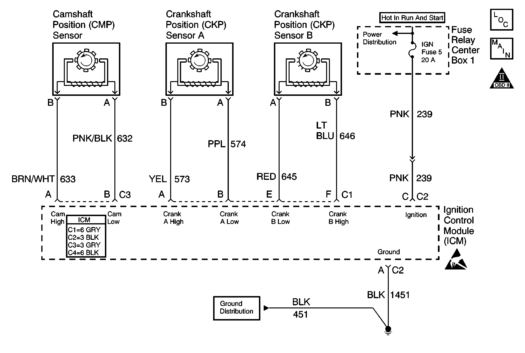
Circuit Description
The diagnostic test checks for CAM reference pulses not received when 4X reference pulses are being received. This indicates a CAM sensor circuit failure and DTC P0340 is set.
Conditions for Running the DTC
| • | DTC P0322 is not set. |
| • | Engine speed is 1600 RPM or less. |
Conditions for Setting the DTC
A CAM reference pulse was not received for 5.3 seconds.
Action Taken When the DTC Sets
| • | The PCM illuminates the malfunction indicator lamp (MIL) on the second consecutive ignition cycle that the diagnostic runs and fails. |
| • | The PCM records the operating conditions at the time the diagnostic fails. The first time the diagnostic fails, the PCM stores this information in the Failure Records. If the diagnostic reports a failure on the second consecutive ignition cycle, the PCM records the operating conditions at the time of the failure. The PCM writes the conditions to the Freeze Frame and updates the Failure Records. |
Conditions for Clearing the MIL/DTC
| • | The PCM turns OFF the malfunction indicator lamp (MIL) after 3 consecutive ignition cycles that the diagnostic runs and does not fail. |
| • | A last test failed, or current DTC, clears when the diagnostic runs and does not fail. |
| • | A history DTC clears after 40 consecutive warm-up cycles, if no failures are reported by this or any other emission related diagnostic. |
| • | Use a scan tool in order to clear the MIL and the DTC. |
Conditions for Clearing the MIL/DTC
| • | The PCM will turn the MIL OFF after three consecutive drive trips that the diagnostic runs and does not fail. |
| • | A last test failed, or current DTC, will clear when the diagnostic runs and does not fail. |
| • | A History DTC will clear after forty consecutive warm-up cycles with no failures of any emission related diagnostic test. |
| • | Use a scan tool to clear DTCs. |
| • | Interrupting PCM battery voltage may or may not clear DTCs. This practice is not recommended. Refer to Clearing Diagnostic Trouble Codes in Powertrain Control Module Description . |
Test Description
The numbers below refer to the step numbers on the diagnostic table.
-
Using Freeze Frame and Failure Records may assist in locating an intermittent condition. Operate the vehicle within the same conditions that you observed in the Freeze Frame and Failure Records.
-
This step tests the camshaft position (CMP) sensor and wiring. If the DMM displays a frequency, then the CMP sensor and wiring are OK.
-
This step tests the output of the ignition control module (ICM). If the DMM displays a frequency, then the ignition module is OK.
Step | Action | Value(s) | Yes | No | ||||||||
|---|---|---|---|---|---|---|---|---|---|---|---|---|
1 | Did you perform the Powertrain On-Board Diagnostic (OBD) System Check? | -- | ||||||||||
Is the CMP transitioning? | -- | Go to Diagnostic Aids | ||||||||||
Does the DMM display a frequency while cranking the engine? | -- | |||||||||||
4 |
Did you find and correct the condition? | -- | ||||||||||
Does the DMM display a frequency? | -- | |||||||||||
6 |
Did you find and correct the condition? | -- | ||||||||||
7 |
Did you find and correct the condition? | -- | ||||||||||
8 | Replace the CMP sensor. Refer to Camshaft Position Sensor Replacement . Is the action complete? | -- | -- | |||||||||
9 | Replace the ICM. Refer to Ignition Control Module Replacement . Is the action complete? | -- | -- | |||||||||
10 |
Important: The replacement PCM must be programmed. Replace the PCM. Refer to Powertrain Control Module Replacement/Programming . Is the action complete? | -- | -- | |||||||||
11 |
Does the scan tool indicate that this test ran and passed? | -- | ||||||||||
12 | Select the Capture Info option and the Review Info option with the scan tool. Does the scan tool display any DTCs that you have not diagnosed? | -- | Go to the applicable DTC table | System OK |
