For 1990-2009 cars only
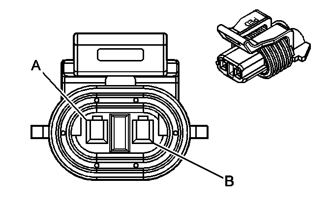
Connector end views show the cavity or terminal locations for all the related 2-pin or larger connectors shown in the system schematic(s). The drawings show the connector's face as seen after the harness connector has been disconnected from a component or mating connector. Unused cavities are left blank in the table.
In addition, the color and part number of the connector body is provided along with the family/series name.
Below is an example of a typical connector end view.

| |||||||
|---|---|---|---|---|---|---|---|
Connector Part Information |
| ||||||
Pin | Wire Color | Circuit No. | Function | ||||
A | PNK | 239 | Ignition Feed | ||||
B | DR GRN/WHT | 428 | Purge Valve Control | ||||
