Poor Heat with Cold Outside Temperatures at Low Engine RPM (Install Auxiliary Coolant Pump)

| Subject: | Poor Heat with Cold Outside Temperatures at Low Engine RPM (Install Auxiliary Coolant Pump) |
| Models: | 1997-1999 Chevrolet Venture |
| 1997-1999 Oldsmobile Silhouette |
| 1997-1999 Pontiac Trans Sport |
| 1999 Pontiac Montana |
| Attention: | Implementation of this Service Bulletin by "GM of Canada" dealers requires prior District Service Manager approval. |
This bulletin is being revised to clarify the parts information in Step 13 under the Correction section and update the Warranty Information. Please discard Corporate Bulletin Number 00-01-38-011B (Section 01 - HVAC).
Condition
Some customers may comment on poor heat in the vehicle passenger compartment at low engine RPM. This condition is most prevalent at outside temperatures below 0° C (32° F).
Cause
The vehicle's heater core may not have sufficient engine coolant flow while the vehicle is idling. Anytime the engine RPM drops to idle speed, the temperature of the heated air may decrease to an unacceptable level even if the engine is already at full operating temperature.
Correction
A service only kit has been released which contains an electric auxiliary coolant pump. The components of this kit will boost coolant flow through the heater core whenever the outside air temperature falls below 0° C (32° F). The service kit is similar in design to the factory installed models on the 2000 model year vehicles. Any 1997-1999 vehicle that comes into the dealership that has not had the auxiliary coolant pump service kit installed and has an insufficient heating condition may need to have a pump kit installed.
Any 1997-1999 vehicle that comes into the dealership that has had an auxiliary coolant pump service kit installed and has an insufficient heating condition should be diagnosed using Heating Insufficient-Auxiliary (SI Document ID 793821) in the 2000 model year Service Information. This diagnostic and the HVAC schematics are compatible for both the installed 1997-1999 service kit and the 2000 OEM auxiliary coolant pumps.
The following procedure contains specific instructions for retrofitting vehicles equipped with the following RPO codes:
| • | C34 -- Air Conditioner with Rear Heater |
| • | C60 -- Air Conditioner, Front |
Procedure
The RPO of the vehicle must be identified (refer to the Service Parts Identification label) to ensure that the correct parts are used. The kit can be installed using automotive hand tools.
- Prep the vehicle and disconnect the negative battery terminal.
- Drain the cooling system. Refer to the Engine Cooling sub-section of Engines in the Service Manual.
- Remove the engine coolant overflow bottle from the left side underhood diagonal brace bar.
- Remove the cruise control module and bracket.
- Remove the left underhood diagonal brace bar and discard.
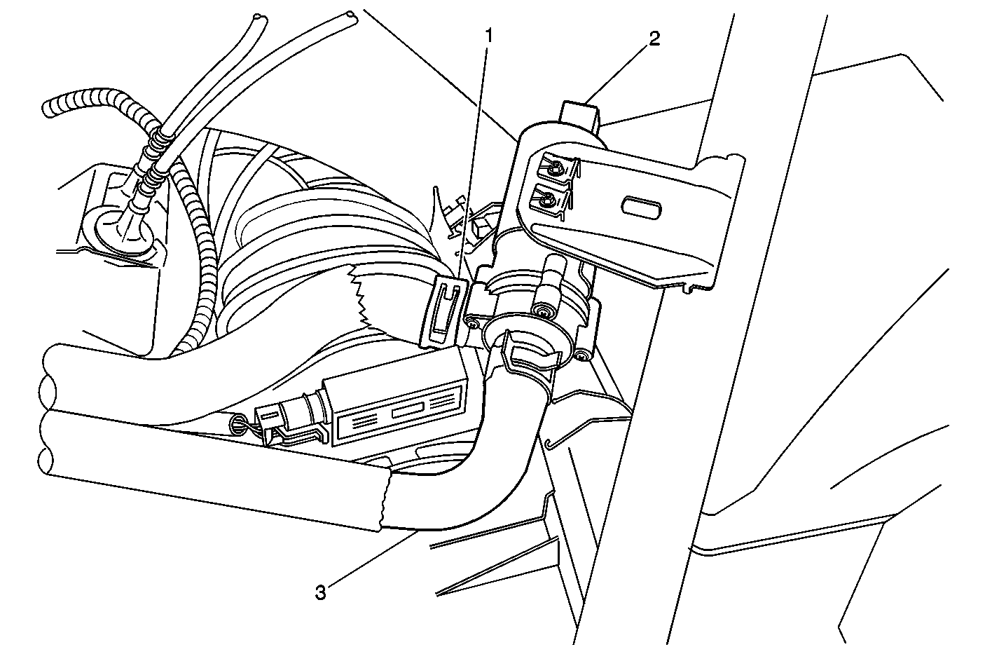
- Mount the coolant pump on the cross brace using a bolt, washer and nut (supplied). Install through the slotted hole (see Figure 1). The brace bar should be oriented with the bracket to the inside of the vehicle and the double bolt holes at the end of the brace to the front of the vehicle.
- Select the required hoses. Each kit contains three hoses. Only two will be used with each application. Select the hose marked with both C34 and C60 as it will be used for both applications. Select the other hose for your application by matching the RPO code with the code on the end of the hose.
- Install and clamp the hoses to the pump nipples. The hose ends are labelled pump outlet and inlet. The outlet of the pump can be identified by a directional arrow molded into the pump body. The paint marks on the hoses should be aligned at the 12:00 position for all hose attachments to ensure correct hose orientation.
- Install the revised brace bar using 3 bolts.
- (C60 ONLY) -- Remove the heater hose from the heater core inlet (bottom fitting).
- (C60 ONLY) -- Install the new heater hose from the heater core inlet to the pump end outlet.
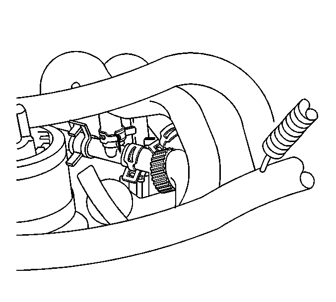
- (C34 ONLY) -- Install the new heater hose from the pump end outlet to the rear heater coolant inlet tee (shown in Figure 2). The hose ends are labelled for flow and attachment point.
- Install the new heater hose, P/N 10441577, from the pump inlet to the engine outlet quick connect fitting (C34 and C60). The new hose comes with a new plastic insert for the fitting. Be sure to remove and discard the old plastic insert from the engine side before installing.
- Connect the wire harness, P/N 15364721, to the coolant pump and route the wire harness from the pump to the area of the left headlight assembly. Pass the harness branch with the edge-of-metal clip through the radiator support behind the left headlight support frame.
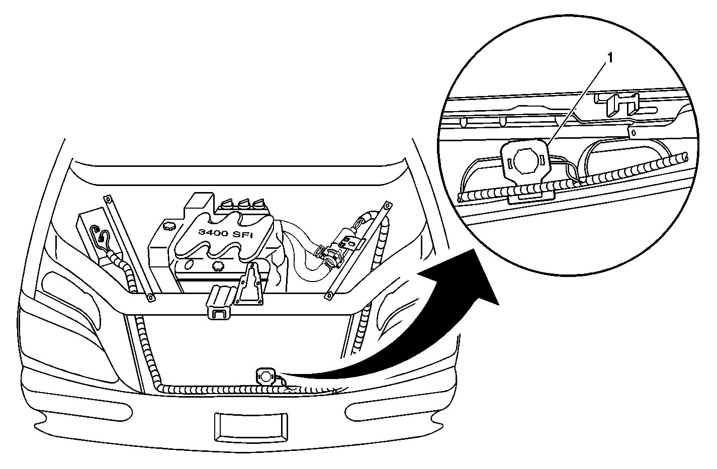
- Attach the ambient Air Temperature Sensor (ATS), P/N 10407728, to the back side of the bumper bar in the approximate location shown in Figure 3. Routing of the harness from the left to the right side of the vehicle should follow the cross car engine harness that is located just behind/below the hood latch mechanism (illustration is only for locating sensor position).
- Connect the harness to the underhood electrical center.
- Install the cruise control bracket.
- Install the cruise control module.
- Install the coolant recovery bottle.
- Fill the cooling system. Refer to the Engine Cooling sub-section of Engines in the Service Manual.
- Connect the negative battery cable to the battery.
Figure 1

Important: Some kits may be equipped with a Bosch® (alternative) pump. If equipped, the attachment of the pump to the brace bar will be with two retaining clips (shown in Figure 1) in place of the bolt, washer and nut arrangement. Attachment of the Bosch® pump will utilize the two inboard holes on the bracket. Pump orientation will be the same as the standard pump.
Important: Hose lubricant may be used in the next step to aid in the installation of the hoses. Use P/N 9985406 if needed for all hose connections.
Tighten
Tighten the diagonal brace bolts at the radiator support to 25 N·m (18 lb ft).
Tighten
Tighten the diagonal brace bolt at the wheelhouse to 47 N·m (34 lb ft).
Important: The hose is marked LWR HTR and PUMP OUTLET at the respective ends.
Figure 2

Important: The heater hose mentioned in the next step is ONLY available as part of the kit listed in the Parts Information below. It is NOT serviceable separately.
Important: The harness branch with the rosebud and edge-of-metal attachment feature is to be connected to the ambient temperature sensor.
Figure 3

| 16.1. | Remove the 68-way connectors (bolted) for I/P and engine harnesses (black and rusty brown color). |
| 16.2. | The new harness has two wires to be connected to the terminals as follows: |
| 16.2.1. | Connect the pink wire (CKT 1239) to cavity D8 of the black colored engine electrical harness (the cavities are marked). |
| 16.2.2. | Connect the black wire (CKT 1050) to cavity B8 of the rusty brown colored I/P harness. |
| Notice: Use care when installing the 68-way connectors. It is possible to abrade or pinch wires, damaging the insulation by improper installation. |
| 16.3. | Assemble the underhood electrical center carefully to avoid damage to the insulation. |
| 16.4. | Use the included wire tie straps to secure all new wiring. |
Tighten
Tighten the bolts to 6 N·m (53 in lb).
Verifying Proper Operation of the Pump
After installing all components of the kit, you must verify the proper operation of the system using the following testing procedure.
- Turn the ignition switch to the RUN position, but DO NOT start the engine.
- Test the coolant pump to ensure that it is not running.
- Disconnect the ATS.
- Use a fused jumper to bridge the connections on the ATS harness. Verify that this action causes the pump to run.
- Reconnect the ATS harness.
Important: The coolant pump should not run at room temperature. The pump should only run below approximately 1.1° C (34° F). If the vehicle is outside, you may utilize the following chart for the specifications of the ambient ATS.
Status Change | Temperature | Tolerance |
|---|---|---|
Open to Closed | 2° C (36° F) | +3° C -2° C (+6° F -4° F) |
Closed to Open | 8° C (47° F) | +2° C -3° C (+4° F -6° F) |
Parts Information
Part Number | Description |
|---|---|
10446377 | Kit, Auxiliary Coolant Pump |
Warranty Information
For vehicles repaired under warranty, use:
Labor Operation | Description | Labor Time |
|---|---|---|
J3580 | Auxiliary Coolant Pump Kit - Install | Use Published Labor Operation Time |
Add: | Diagnosis |
