INSUFFICIENT LATERAL SUPPORT OR CENTER CONSOLE ALIGNMENT

MODELS/YEARS 1990 TORONADO AND TROFEO
Some early built Oldsmobile Toronados and Trofeos may exhibit a condition of insufficient lateral support of the center console. The console may appear to be loose and allow more than normal movement from side to side and may not properly align with the instrument panel. To repair this condition, install the components as necessary, from either update kit listed at the end of this bulletin, using the following procedures:
To perform outlined repair the following will be needed:
1. Proper Kit, listed at end of bulletin, based on VIN number.
2. 4 (1/8 x 1/4) pop rivets or 4 pan head sheet metal screws.
3. 1 (3" x 1 ") piece of sheet metal, cut from unpainted body shop flat stock.
4. 1 (2 1 /2" x 1 ") piece of sheet metal, cut f rom unpainted body shop flat stock.
5. 2 - 1 inch square pieces of hook and loop fastener i.e., 3M Part Number - 06480 or equivalent, obtained locally.
6. 1 hot melt glue gun and glue stick.
UPDATE PROCEDURES:
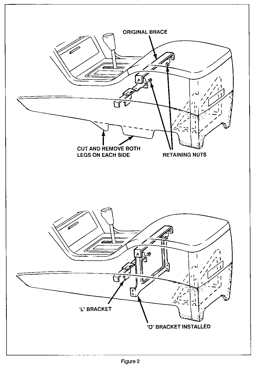
1. Remove the console per instructions in Service Manual Section 8C. If the two front legs of the console structure are present as in Figure 2, remove them by scribing a groove on the interior of the console using a straight edge and breaking the legs off with pliers. NOTE: Do not cut the carpeting from these areas after removing the legs.
2. Remove the four nuts and the existing brace (Figure 2).
3. Position the new bracket from the kit (Figure 2) into the console.
4. Mark the position of the four additional lower holes in the new bracket on the console interior surface by pressing hard with a sharp center punch that indents to the outer surface.
5. Remove the bracket.
6. Peel back the carpeting on the outside area where hole positions were marked.
7. Drill 1/8" holes in the console at the marked positions.
8. Position the bracket in the console.
9. Secure the bracket using rivets in the new holes with 1/8" x 1/4" rivets or sheet metal screws.
10. Install the original retaining nuts in the top and the original console light switch from the old bracket.
11. Reglue carpeting to console using 3M General Trim Adhesive part number - 08080 or equivalent.
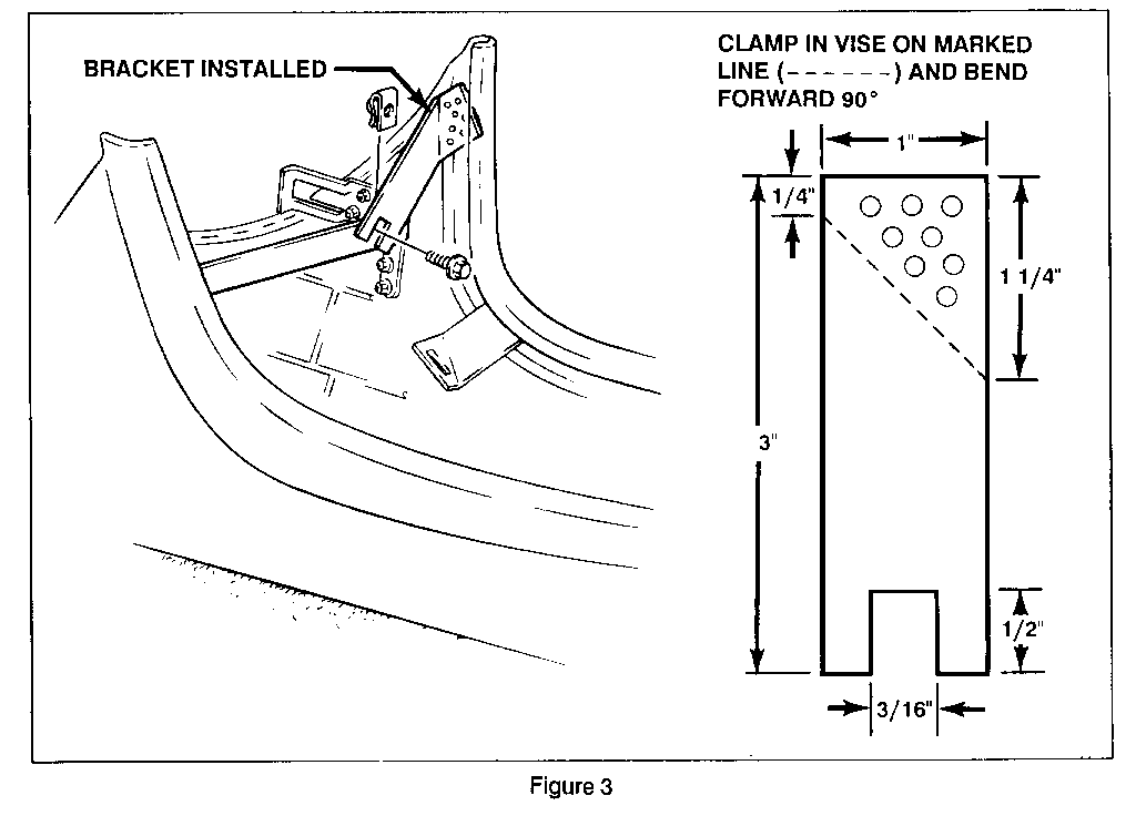
12. If needed, additional strength and adjustments to the right front corner of the console may be obtained by installing a fabricated bracket (Figure 3) using the following procedure:
Using Figure 3 as a template, mark the 3" x 1 " strip of sheet metal.
Cut slot as indicated in Figure 3, 1/2" deep by 3/16" wide.
Using a 1/8 inch drill, make several holes in the top area.
Clamp the metal strip in a vise and bend (90 degrees) as indicated in Figure 3.
Place the bracket in its installed position, slotted end downward and upper end snug against the bottom of the existing plastic bracket and bend as necessary to align the slot to fit over the right mounting hole on the console brace (Figure 3).
Apply sufficient amounts of 3M 05900 (Flexible Parts Repair) adhesive or equivalent to the console area that will retain the bracket (Figure 3).
Press bracket into place allowing adhesive to squeeze through the punched holes.
Clamp the bracket to the center brace using vise grip pliers and allow the adhesive to set.
The following steps should be performed while waiting for the adhesive to set.
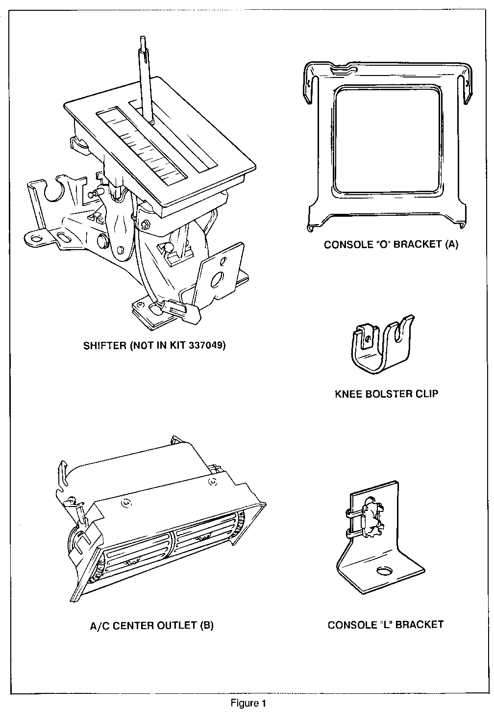
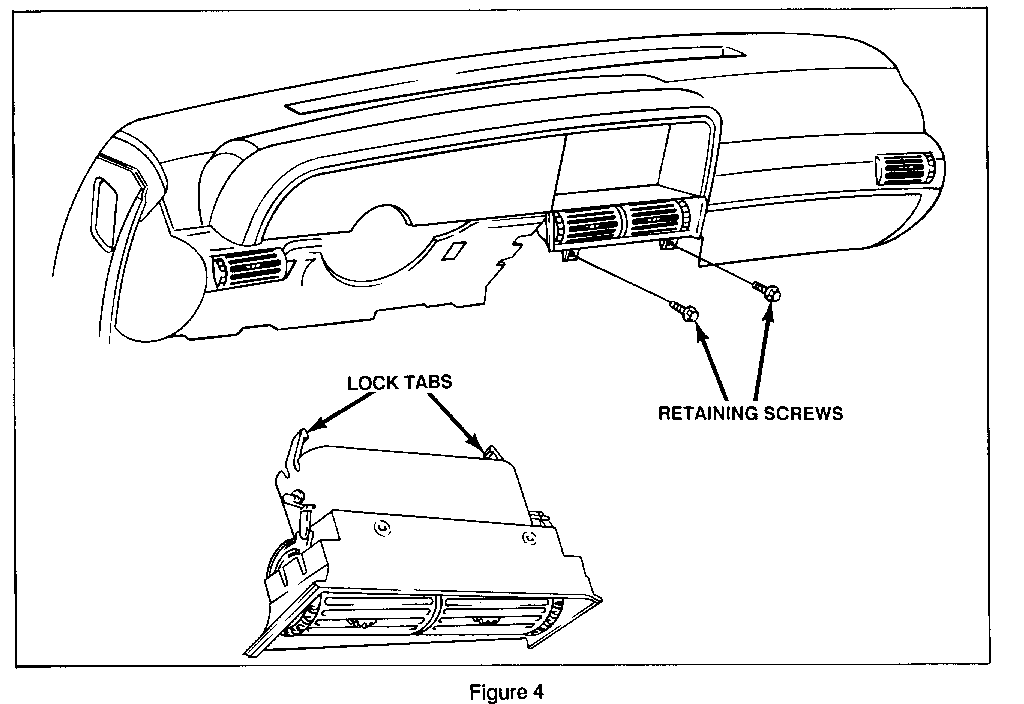
13. With the console removed, remove the center A/C outlet and install the new outlet supplied in the kit.
Remove the two attaching screws at the bottom of the outlet Pull outward on the center outlet If the outlet separates, also pull out the innerportion prior to installing the new outlet.
NOTE: If the A/C outlet is not being replaced, do not remove the original outlet.
Install the new center outlet and tighten the retaining screws.
14. If the VIN is prior to LU301438, use kit (337048). The new shifter has a lowered mounting bracket to allow for better alignment of the console and PRNDL trim plate. Replace the shifter using the following procedure:
Disconnect PRNDL light wiring.
Remove shift cable retaining clips and disconnect shift cables from the shifter assembly.
Remove the four shifter retaining nuts.
Install shift cables to new shifter.
Position shifter to floor pan.
Tighten retaining nuts.
Reconnect the PRNDL light wiring.
15. Install the new "L" bracket (Figures 1 and 2) supplied in the kit if needed. This part may not have been installed on some early built Toronados.
NOTE: Do not tighten the "L" bracket until the console is installed.
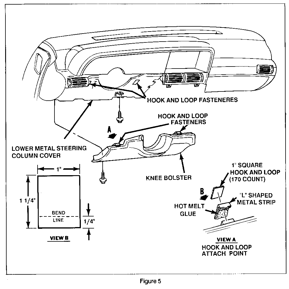
16. To improve retention of the knee bolster, perform the following prior to re-installing the console;
Remove knee bolster (Section 8C of service manual).
Remove bushing from lower right attach point on knee bolster.
Peel back and remove hook and loop fastener square from the knee bolster and from the instrument panel carrier.
Rub off any residue left behind by the removed hook and loop fasteners. DO NOT USE ANY SOLVENT CLEANERS AS DAMAGE TO PARTS WILL RESULT!
Gently sand both the knee bolster attach points and the instrument panel carrier attach points with a fine sandpaper.
Cut the (2 1/2" x 1 ") piece of sheet metal in half to make two (1 1/4" x 1") pleces.
Clamp each of the 1 1/4" x 1" pieces of metal in a vice and bend to produce an "L" shape (see Figure 5).
Clean the "L" shaped pieces with alcohol and wipe clean and dry with a lint free cloth.
Apply a liberal amount of hot melt glue (from any hot melt glue gun) to the "L" shaped pieces of metal and secure to the knee bolster (see Figure 5).
NOTE: The use of a glue with petroleum distillates may dissolve the knee bolster beyond repair.
Secure the course hook and loop squares to the two metal "L" pieces (see Figure 5).
Secure the fine hook and loop squares to the instrument panel carrier (see Figure 5).
Install knee bolster clip (see Figure 1) to lower right knee bolster attach point on I/P steering column reinforcement plate. Using appropriate pan head screw.
Position knee bolster to I/P with lower edge of knee bolster into knee bolster clip. Fold knee bolster into position while aligning bolster in opening. Press hook and loop ATTACHMENT firmly in place. Replace screw in lower left corner of knee bolster.
17. Install console per instructions in Section 8C of the Service Manual.
18. Using the slotted end of the new bracket, align the right front corner for the best possible fit and tighten.
19. Assure that the best possible alignment to the instrument panel has been made prior to installing the trim plate.
WARRANTY INFORMATION:
Available kits (Figure 1)
VIN Kit Number --- ---------- Prior to LU301438 337048 (w/shifter) LU301439 - LU302110 337049 (without shifter)
Kit Number Labor Operation Labor Time Trouble Code ---------- --------------- ---------- ------------ 337048 T4656 1.6 hours 92 337049 T4657 1.3 hours 92
Dealers will not be billed for parts supplied in the update kits. Claims should be submitted as labor only with no parts cost.
Parts Ordering Information:
Kits may be ordered by mail form, or by telephone from:
TUAR Company 5365 Hill 23 Drive Flint, Mi. 48501 - 0354 313-239-5552
All kits requested will be shipped prepaid UPS within 48 hrs.
Dealers must provide the following information;
Dealer Code
Dealer Name Address
Requested by
VIN
Mileage
To be installed in Stock (S) Demo (D) Customer (C) vehicle.
General Motors bulletins are intended for use by professional technicians, not a "do-it-yourselfer". They are written to inform those technicians of conditions that may occur on some vehicles, or to provide information that could assist in the proper service of a vehicle. Properly trained technicians have the equipment, tools, safety instructions and know-how to do a job properly and safely. If a condition is described, do not assume that the bulletin applies to your vehicle, or that your vehicle will have that condition. See a General Motors dealer servicing your brand of General Motors vehicle for information on whether your vehicle may benefit from the information.
