CONVERTIBLE CONTROL ROD BREAKAGE REPLACE CAM ASSY.

SUBJECT: CONVERTIBLE CONTROL ROD BREAKAGE (REPLACE CAM ASSEMBLY)
VEHICLES AFFECTED: 1990 "E" MODEL
Some 1990 Reatta convertibles may experience a condition of the convertible top control rods breaking. This condition may be caused by improper top operation, control rods incorrectly adjusted, or a damaged cam assembly. To repair this condition use the following service procedure:
NOTE: If control rod is broken, use extreme care when operating top. The #5 bow extension must be physically moved in and out while operating top to avoid causing damage to quarter panel horn area.
1. Remove the quarter trim panel on the side of the broken control rod.
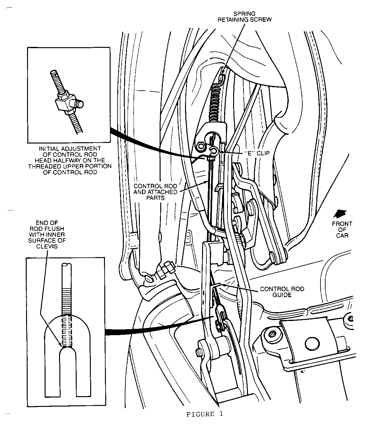
2. Raise the #5 bow to a vertical position and release front header latches. Remove old control rod upper spring retaining screw using a #25 torx head bit on a 1/4" drive swivel head ratchet. Remove "E" clip retaining control rod head to actuator lever. Refer to Figure 1.
3. Remove lower clevis pin and clevis. Remove the two screws retaining the control rod guide using a #15 torx head and remove guide. Refer to Figure 1.
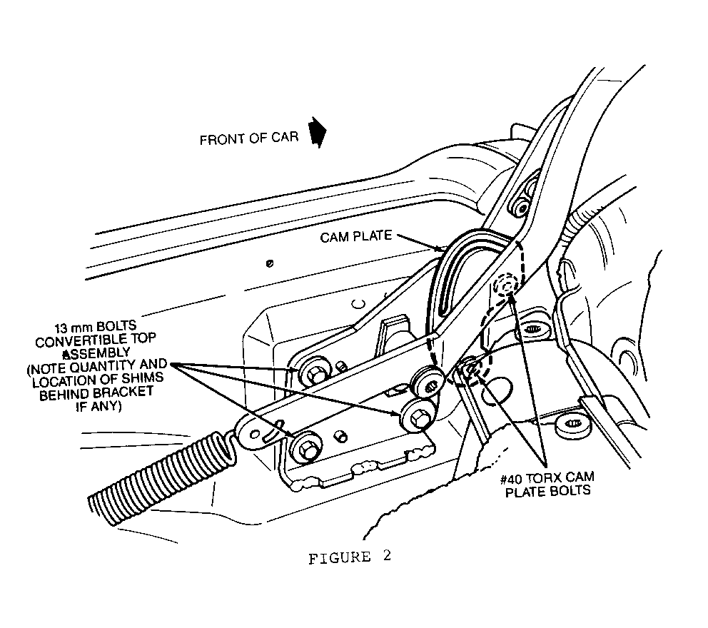
4. Remove the three 13mm head bolts holding the convertible top assembly main pivot bracket to the car. Note location and quantity of any shims installed between main pivot bracket and mounting surface. Pry inboard on the main pivot bracket to clear the dowel pins and move the top assembly rearward. Refer to Figure 2.
5. Replace the cam assembly with P/N 3635176 using a #40 torx head bit. Refer to Figure 2.
6. Install the main pivot bracket over dowel pins and tighten the attaching bolts.
NOTE: If shims are present between the main pivot bracket and mounting surface, reinstall shims in the same location as removed.
7. Preset the new control rod, P/N 3635177 (LH) or 3635178 (RH), head adjustment half way on the threaded upper portion of the control rod using the two 5mm nuts on either side of the head. Refer to Figure 1.
8. Remove "E" clip and actuator lever from new control rod.
9. Remove clevis from new control rod and thread rod through guide. Thread clevis back onto rod until end of rod is flush with inner surface of clevis. Refer to Figure 1.
10. Install upper spring retaining screw and tighten.
11. Grasp rod with vise-grip pliers and pull downward until clevis pin can be inserted through clevis and cam slot. Verify clevis is aligned on rod properly so that the clevis slips over cam with no side-to-side binding. Install clevis pin safety clip.
12. Install control rod guide and tighten screws.
13. Move #5 bow extension inboard until control rod head can be engaged into actuator lever and install "E" clip.
14. Lubricate cam slot and clevis pin with heavy grease.
15. Lower rear bow to 450 angle and carefully lower top into well while watching clevis to ensure smooth operation through cam slot. If clevis starts to bind or hang up in cam slot, raise top and adjust control rod head downward (shorten rod) using the two 5mm nuts on either side of the head until smooth operation is attained.
NOTE: A click may be heard at the beginning of the clevis travel and should be considered normal.
16. Install quarter trim panel.
Use the most applicable Labour Operation and Time from the Canadian Labour Time Guide.


General Motors bulletins are intended for use by professional technicians, not a "do-it-yourselfer". They are written to inform those technicians of conditions that may occur on some vehicles, or to provide information that could assist in the proper service of a vehicle. Properly trained technicians have the equipment, tools, safety instructions and know-how to do a job properly and safely. If a condition is described, do not assume that the bulletin applies to your vehicle, or that your vehicle will have that condition. See a General Motors dealer servicing your brand of General Motors vehicle for information on whether your vehicle may benefit from the information.
