Liftgate Does Not Pop Open On First Try (Align Liftgate)

| Subject: | Liftgate Does Not Pop Open On First Try (Align Liftgate) |
| Models: | 2001-2005 Pontiac Aztek |
This bulletin is being revised to update the model years. Please discard Corporate Bulletin Number 03-08-66-005 (Section 08 -- Body and Accessories).
Condition
Some customers may comment that the liftgate does not pop open on the first try. The liftgate release or key fob must be used repeatedly to open the liftgate. This condition occurs more often in cold weather.
Cause
This condition may be caused by misalignment of the liftgate hinges, the strikers or the latches.
Correction
Technicians are to align the liftgate using the following procedure:
Important: All dimensions checked in this procedure are measured using a caliper with internal measuring jaws. The caliper may be of the dial or digital type. They are available from Kent-Moore (1-800-GM-TOOLS). The tool numbers are J-39768 (Dial Caliper) and J-39776 (Digital Caliper) . If these tools are not available, a steel ruler may be used; but it is more difficult to get accurate measurements. Accurate measurement is very important in the correction of this condition.
- Open the liftgate.
- Check the opening and closing effort and alignment of the endgate. Do not adjust the endgate unless it is absolutely necessary.
- Close the endgate and liftgate.
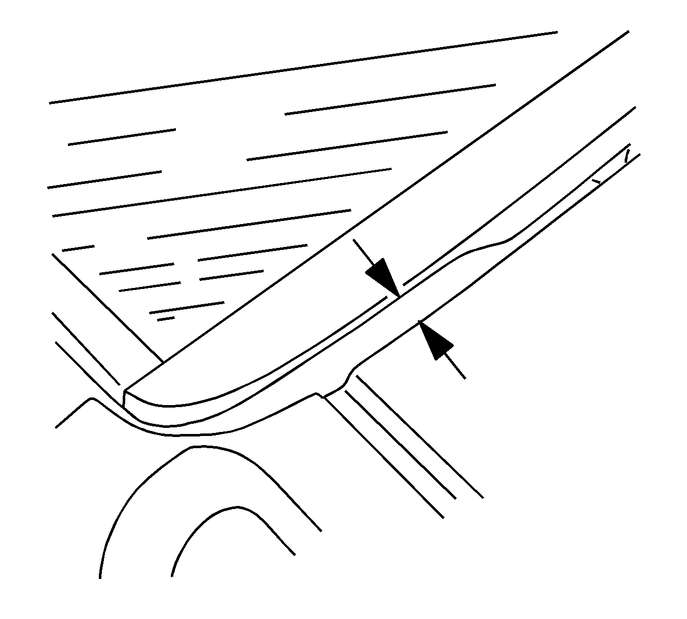
- Measure the gap between the forward edge of the liftgate and the roof. The gap is measured on both sides of the vehicle at the forward corners of the liftgate. Refer to the illustration above for the proper location. The ideal distance between the two panels is 14 mm (0.5512 in) with a tolerance of +/- 1 mm (0394 in). The gap should be the same on both sides of the vehicle. Record the amount necessary to move the liftgate to attain the desired specification for each side.
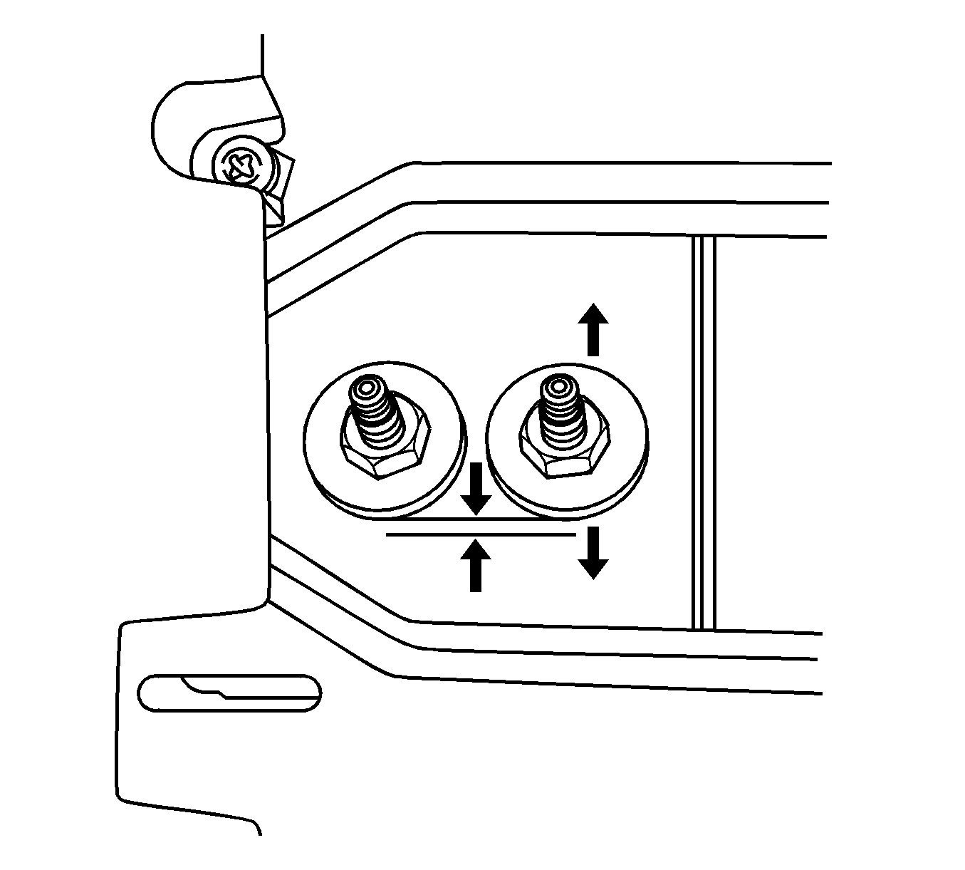
- If the liftgate hinge needs to be moved forward or backward, remove the garnish molding at the rear of the headliner that covers the liftgate hinges. Refer to the Garnish Molding Replacement - Rear Upper Aztek procedure in SI. Make a reference mark around the current location of the nuts on the liftgate hinges. Refer to the illustration above and draw a line that is the previously recorded distance that the liftgate hinge must be moved, either in front of or behind the liftgate hinge nuts. Loosen the liftgate hinge nuts, on one side at a time, and WITH THE LIFTGATE CLOSED, move the liftgate hinge forward or backward as necessary. Recheck the gap between the liftgate and the roof on both sides of the vehicle and adjust the liftgate hinges again if necessary. Try to come as close as possible to the ideal gap of 14 mm (0.5512 in).
- With the endgate and liftgate closed, check the side to side alignment of the liftgate to the quarter panels. The liftgate to quarter panel alignment should only be adjusted if it is absolutely necessary. The side to side adjustment is made by loosening the nuts on the hinge that is located at the forward edge of the liftgate. They are visible when the liftgate is opened. Try to center the liftgate from side to side between the quarter panels.
- Remove the interior trim panel on the lower part of the liftgate to gain access to the liftgate strikers. Refer to the Trim Panel Replacement - Lift Gate Aztek procedure in SI.
- Remove the trim panel from the endgate. Refer to the Trim Panel Replacement - End Gate procedure in SI.
- While working from inside the vehicle, pull the liftgate down to see if the liftgate strikers make contact with the latches in the endgate at the same time. Apply the closing effort to the center of the liftgate so that the liftgate is not being twisted out of alignment when it is closed. If the strikers do not make contact with the latches at the same time, grab the liftgate and carefully twist the entire liftgate. You will actually put a small bend in the liftgate itself to bring one corner closer to the liftgate latches. Pull the liftgate down again, from the center, to see if the strikers are making contact with the latches at the same time. Readjust the liftgate if necessary.
- Pull the liftgate down so that the liftgate strikers just touch the liftgate latches. Look at the liftgate strikers to see if they are centered in the U-shaped opening of the liftgate latch.
- If the liftgate strikers are not centered in the U-shaped opening, loosen the liftgate striker bolts. Center the liftgate strikers in the U-shaped opening of the liftgate latch and then retighten the liftgate striker bolts.
- Check the liftgate striker alignment as it enters the U-shaped opening of the liftgate latch as the liftgate is opened and closed. If the liftgate striker touches the sides of the liftgate latch, it will be necessary to rotate the liftgate latch which is located in the endgate.
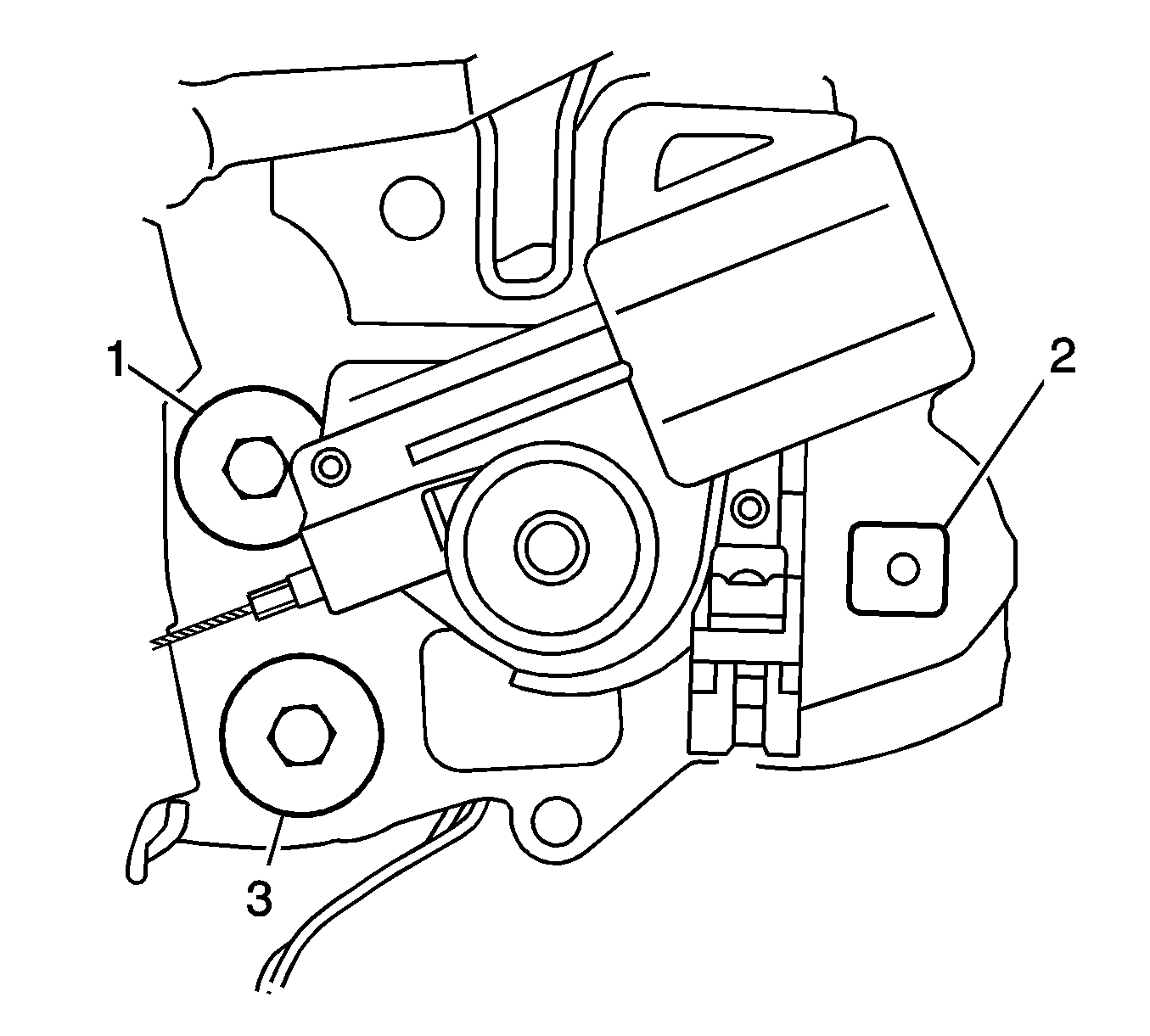
- To rotate the liftgate latch, refer to the illustration above for the bolt numbering described in this step. Remove the bolt from location number two on the liftgate latch. Inspect the centering of the bolt hole threads in the square opening of the liftgate latch. If the bolt hole is not centered, loosen the bolts at locations one and three slightly and rotate the liftgate latch to bring the bolt hole to the center of the square opening in the liftgate latch. Tighten all three liftgate latch bolts. Repeat this procedure on the liftgate latch on the opposite side of the vehicle if necessary.
- Recheck that the liftgate strikers make contact with the liftgate latches at the same time. Readjust the liftgate if necessary.
- Recheck that the liftgate strikers are centered in the liftgate latches. Readjust the liftgate strikers if necessary.
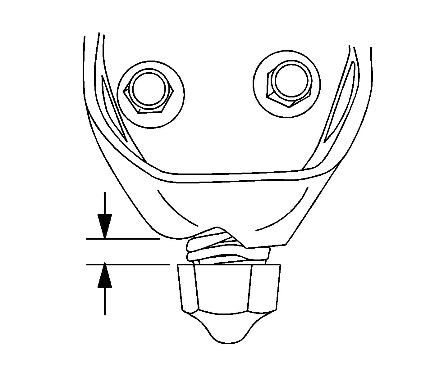
- Open the liftgate and locate the rubber bumpers on either side of the liftgate. Measure the distance between the flat on the rubber bumper and the flat on the bracket that holds the bumper. Refer to the illustration above that shows the proper measurement location for the bumper on the right side of the vehicle. Take the measurement on the rear side of the right bumper and on the forward side of the left bumper. The measurement should be 5 mm +/- 1 mm (0.1968 in +/- 0.0394 in). Adjust the bumpers in or out as necessary.
- Apply GM Super Lube, P/N 12346241 (in Canada, P/N 10953474), to both liftgate latches.
- Reinstall the endgate trim panel. Refer to the Trim Panel Replacement - End Gate procedure in SI. Close the liftgate slowly and watch to see if the liftgate strikers rub on the endgate trim panel. If the liftgate strikers rub on the endgate trim panel, use a file to remove a small amount of material from the endgate trim panel to provide clearance for the liftgate strikers.
- Reinstall the interior trim panel on the liftgate. Refer to the Trim Panel Replacement - Lift Gate Aztek procedure in SI.
- Reinstall the garnish molding at the rear of the headliner. Refer to the Garnish Molding Replacement - Rear Upper Aztek procedure in SI.
- Please advise your customer to always close the liftgate with the closing effort applied to the center of the liftgate. If the closing effort is applied to one side or a corner, it may twist the liftgate out of alignment.


Parts Information
Part Number | Description | Qty |
|---|---|---|
12346241 (US) 10953474 (Canada) | Super Lube | 1 |
Warranty Information
For vehicles repaired under warranty, use:
Labor Operation | Description | Labor Time |
|---|---|---|
B5700* | Align, Liftgate-Endgate - Adjust | 1.0 hr |
*This is a unique labor operation number for bulletin use only. This number will not be published in the Labor Time Guide. | ||
