EXPLANATION OF SYSTEM OPERATION C3I

VEHICLES AFFECTED: 1986-1988 "A", 1986-1987 "C" AND 1986-1988 "H" (VIN CODES 3 OR B)
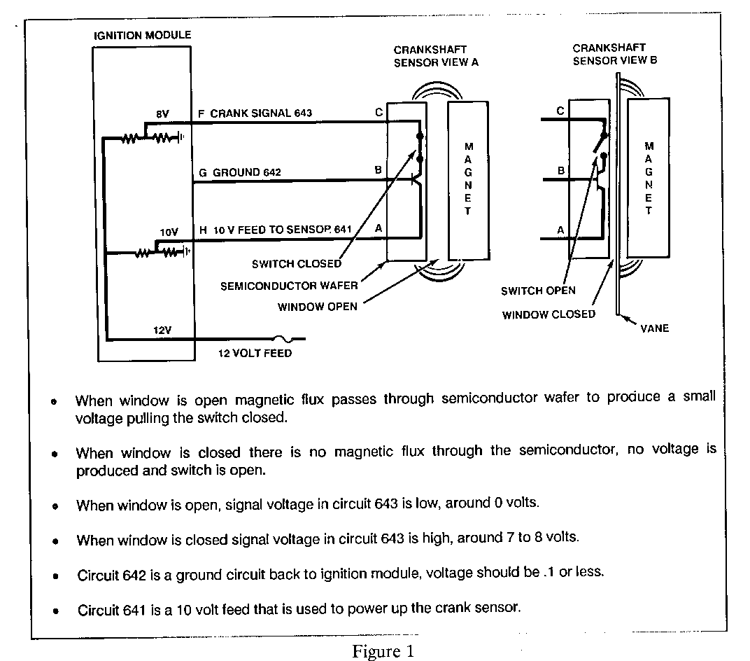
The crank sensor is a hall-effect switch that has three electrical connections. The sensor is triggered by the interrupter ring attached to the crankshaft balancer pulley. The interrupter ring has three windows equally spaced. Therefore the ignition module cannot detect which of the three signals it should assign to which ignition coil. For that information a camshaft sensor is used. The crankshaft signal is also used by the ECM for engine r.p.m.'s.
This article will not go through all of the electronics inside the crank sensor. Just remember, when the interrupter window is closed, the hall-effect sensor will not produce a voltage or allow current flow. The crank sensor signal in Circuit 643 from the ignition module will be "high", around 7 to 8 volts.
When the interrupter window is open, the hall-effect sensor will produce a very small voltage and current flow. This will close the switch in the hall-effect sensor, pulling the signal voltage in Circuit 643 from the ignition module, "low" around .1 of a volt. The switch inside the hall-effect is a transistor. In Figure 1, we will show an on/off switch.
The camshaft sensor is a hall-effect switch with three electrical connections. A magnetic interrupter is used to trigger the sensor. The cam sensor will pulse one time for every two revolutions of the crankshaft. This is the synchronization pulse signal used to indicate crankshaft position.
The voltage in the cam signal Circuit 633 is normally "high" around 7 to 8 volts. When the cam sensor is turned on by the magnetic flux from the interrupter magnet,it will produce a small voltage, close the switch in the cam sensor and pull the signal voltage in Circuit 633 from the ignition module, "low" around .1 volt. After the magnet passes the sensor it will turn off. The switch will open and the cam sensor signal voltage in Circuit 633 will go "high", around 7 to 8 volts.
SYSTEM OPERATION
The camshaft sensor signal voltage from Terminal K of the ignition module Circuit 633 will be toggled low when the magnetic interrupter triggers the cam sensor. This will be when No. 1 cylinder is around 25 degrees after top dead centre. The ignition module monitors the voltage from Terminal F of the ignition module circuit 643 to the crank sensor. When the ignition module sees the voltage in Circuit 643 toggle low after the cam sensor signal in Circuit 633 has been toggled low, it will fire the 3/6 coil to produce spark to the spark plugs. After the syc-pulse signal the ignition module will maintain the correct sequence to fire the spark plugs. The crank sensor signal is sent to the ECM terminal B5 circuit 430 reference high from Terminal C of the ignition module.
The cam sensor signal is sent to the "All" Terminal of the ECM, Circuit 630 from Terminal J of the ignition module. When the ECM sees the reference high signal on Circuit 430, it will pulse the fuel injectors simultaneously (all at once). The ignition module will trigger the ignition coil and fire the spark plugs. Remember, with this system it can take up two revolutions to get the syc-pulse needed to trigger the ignition coil and fuel injectors.
Around 400 r.p.m.'s a 5 volt signal is sent out on the bypass line from the ECM terminal D5 to Terminal B of the ignition module Circuit 424. This will put the system into electronic spark timing (E.S.T.) and the ECM will now control spark timing advance.
Also, around 400 to 600 r.p.m.'s, the ECM will use the cam sensor signal from Terminal J of the ignition module (Terminal "All" of the ECM) Circuit 630 and go to sequential fuel injection.
DIAGNOSIS - 1987 and 1988 3.8L C3I
1. Make sure ignition module has a good ground. (See PSB 87-8-139)
2. Make sure electrical connections at ignition module, crank and cam sensor are tight. (See PSB 88-8-117).
3. If crank and cam sensor signal voltages do not toggle high and low while cranking, engine will not start. Signal voltage should be around 7 to 8 volts "high" and toggle "low" to around 1/2 volt. If voltage does not toggle low and high, the ignition module will not pick the signal up as a toggle. The ignition module will not fire the spark plugs or send the reference high signal to the ECM.
4. If the crank sensor signal voltage stops toggling while the engine is running, it will stall.
5. Cam Sensor
A. The engine will not start if the cam signal is not toggled "high" and "low" because the ignition module has not received a synchronization pulse. Therefore the ignition module does not know which coil to trigger.
B. If the engine is running and the cam signal stops toggling "high" to "low", one of two different conditions will happen.
1. Signal remains "High"
a. System will go to simultaneous fuel injection, will stay running.
b. "Service Soon" light will come "on".
c. Code 41 will be set.
2. Signal remains "Low"
a. If engine is running, engine will stall.
b. If signal remains "Low", it will not restart.
6. Crank and cam sensors must have voltage to power up the sensor, signal voltage and a ground.
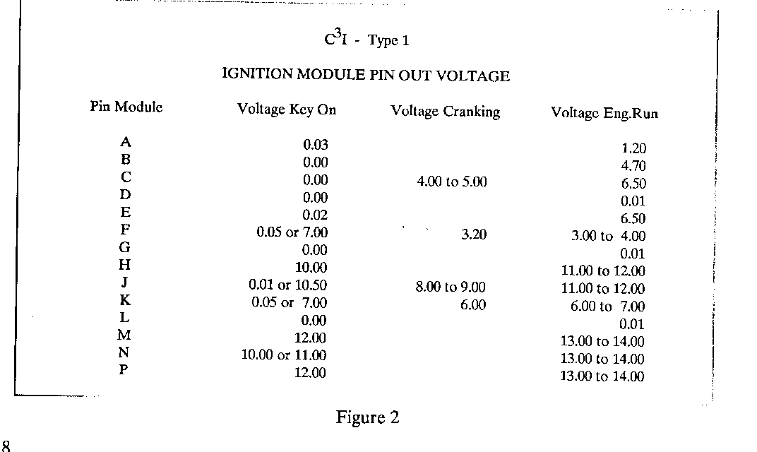
C3I - Type 1 IGNITION MODULE PIN OUT VOLTAGE
Pin Module Voltage Key On Voltage Cranking Voltage ---------- -------------- ----------------- Eng.Run ------- A 0.03 1.20 B 0.00 4.70 C 0.00 4.00 to 5.00 6.50 D 0.00 0.01 E 0.02 6.50 F 0.05 or 7.00 3.20 3.00 to 4.00 G 0.00 0.01 H 10.00 11.00 to 12.00 J 0.01 to 10.50 8.00 to 9.00 11.00 to 12.00 K 0.05 or 7.00 6.00 6.00 to 7.00 L 0.00 0.01 M 12.00 13.00 to 14.00 N 10.00 or 11.00 13.00 to 14.00 P 12.00 13.00 to 14.00
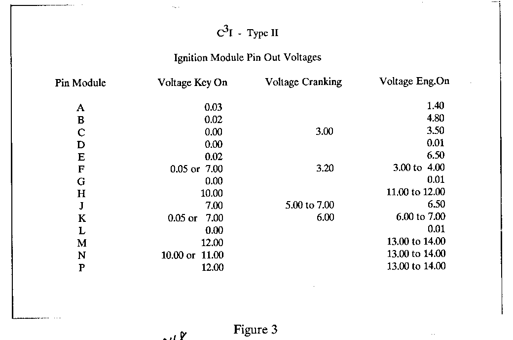
C3I - Type II Ignition Module Pin Out Voltages
Pin Module Voltage Key On Voltage Cranking Voltage ---------- -------------- ---------------- Eng.On ------ A 0.03 1.40 B 0.02 4.80 C 0.00 3.00 3.50 D 0.00 0.01 E 0.02 6.50 F 0.05 or 7.00 3.20 3.00 to 4.00 G 0.00 0.01 H 10.00 11.00 to 12.00 J 7.00 5.00 to 7.00 6.50 K 0.05 or 7.00 6.00 6.00 to 7.00 L 0.00 0.01 M 12.00 13.00 to 14.00 N 10.00 or 11.00 13.00 to 14.00 P 12.00 13.00 to 14.00


General Motors bulletins are intended for use by professional technicians, not a "do-it-yourselfer". They are written to inform those technicians of conditions that may occur on some vehicles, or to provide information that could assist in the proper service of a vehicle. Properly trained technicians have the equipment, tools, safety instructions and know-how to do a job properly and safely. If a condition is described, do not assume that the bulletin applies to your vehicle, or that your vehicle will have that condition. See a General Motors dealer servicing your brand of General Motors vehicle for information on whether your vehicle may benefit from the information.
