Underbody
Inspect vehicles with a bent frame or a sprung frame for the following conditions:
| • | The proper frame alignment |
| • | The steering geometry |
| • | The wheel alignment |
Place the vehicle on a flat and level floor in order to make accurate measurements.
Determine the vehicle measurements using the following methods:
| • | The tram gage method |
| • | The three-dimensional method |
Tram Gage Method
Use a tram gage as a quick reference in order to determine the vehicle damage. Use a tram gage set with a vertical pointer capable of reaching 914 mm (36 in).
Measure the engine compartment components from point to point with the vertical pointers equally set.
For other components, measure in the following ways with the vertical pointers set as specified for each point:
| • | Measure on the horizontal plane or on the datum line. |
| • | Measure parallel to the underbody. |
Measure dimensions in order to gage holes in the following ways:
| • | Measure to the centers of the holes, unless otherwise specified. |
| • | Measure flush to the adjacent surface metal, unless otherwise specified. |
Cross-check the diagonal dimensions in order to verify the dimensional accuracy of the vehicle underbody.
Three-Dimensional Method
Using the appropriate repair equipment for measuring structural repair, measuring the following at the same time:
| • | Multiple points of length |
| • | Multiple points of height |
| • | Multiple points of width |
Measure 2/3 of the vehicle body in order to obtain accurate comparisons to the vehicle structure.
The universal measuring systems combine the equipment and the techniques used in order to make the three-dimensional measurements of the underbody and the upper body .
The universal system provides accurate measurements of the following dimensions at the same time:
| • | The length |
| • | The width |
| • | The height |
Underbody Dimensions - Bottom View
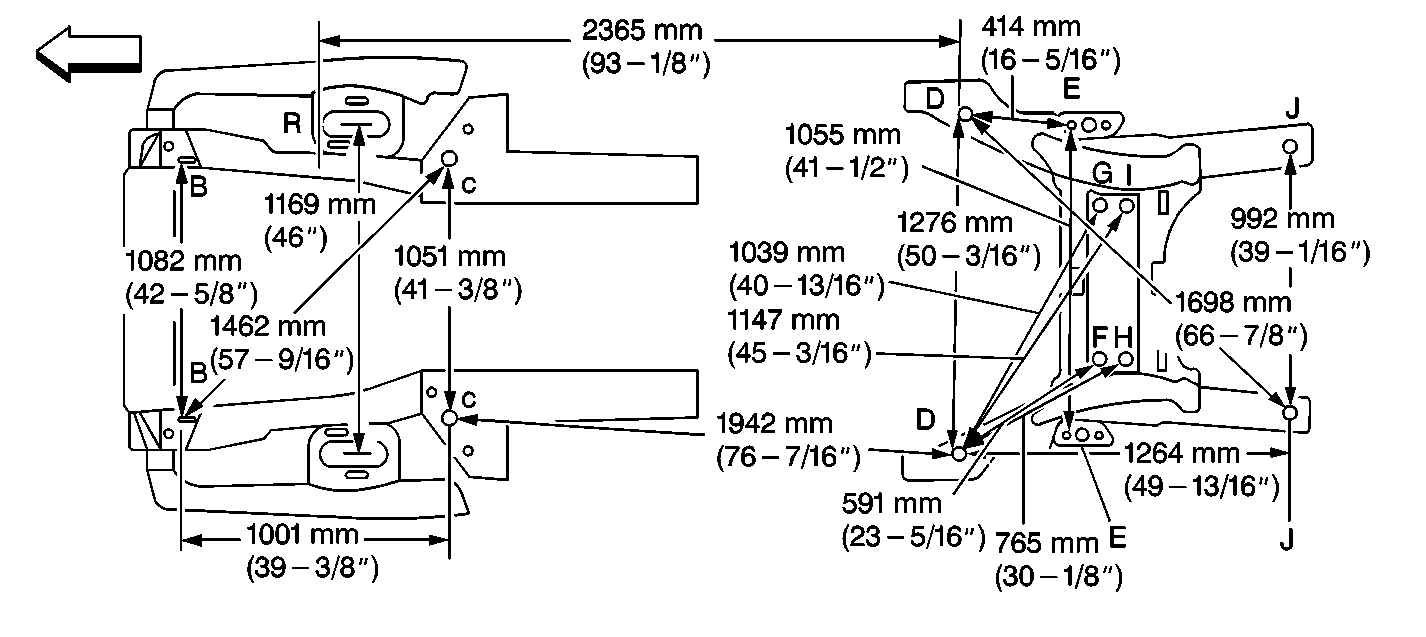
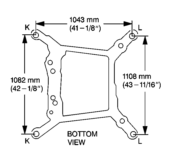
Frame Dimensions - Bottom View
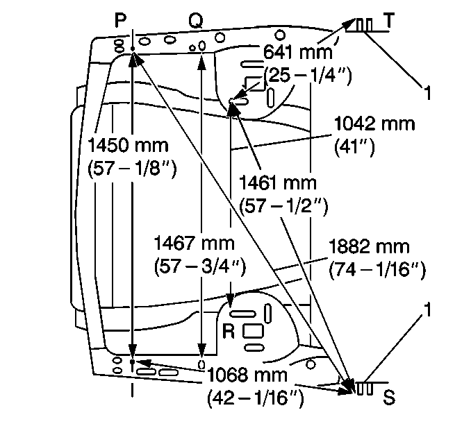
Underhood Dimensions - Top View
Frame Dimensions - Side View
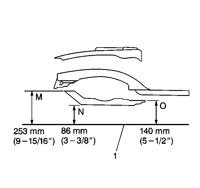
Body Side Dimensions - Side View
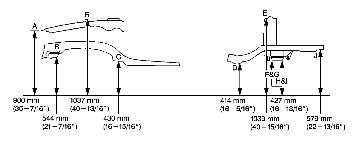
The following table describes the identified points of measurement found in the above graphics:
| • | Underbody Dimensions-Bottom View |
| • | Frame Dimensions-Bottom View |
| • | Frame Dimensions-Side View |
| • | Underhood Dimensions-Top View |
| • | Body Side Dimensions-Side View |
Reference | Horizontal Surface | Vertical Surface | Location |
|---|---|---|---|
A | The outboard and the forward edge of the lip | The lower surface at the corner | The upper fender rail of the engine compartment |
B | The center forward edge of the 22 mm (7/8 in) long slot | The lower surface | The side rail of the engine compartment at the forward frame mount locations |
C | The center of the 18 mm (11/16 in) hole | The lower surface | The side rail of the engine compartment at the cowl which connects to the side rail lower brace |
D | The center of the 20 mm (13/16 in) gage hole | The lower surface | The rear longitudinal rail |
E | The center and the leading edge of the strut forward mounting slot | The lower surface | The rear strut tower |
F | The radius of the forward edge of the crossbar | The centerline of the crossbar lower control arm bolt hole | The rear compartment pan crossbar |
G | The radius of the forward edge of the crossbar | The centerline of the crossbar lower control arm bolt hole | The rear compartment pan crossbar |
H | The radius of the rearward edge of the crossbar | The centerline of the crossbar lower control arm bolt hole | The rear compartment pan crossbar |
I | The radius of the rearward edge of the crossbar | The centerline of the crossbar lower control arm bolt hole | The rear compartment pan crossbar |
J | The center of the 26 mm (1 in) gage slot | The lower surface | The rear longitudinal |
K | The center of the bolt | The lower surface | The forward bolt of the frame mount |
L | The center of the bolt | The lower surface | The rearward bolt of the frame mount |
M | Forward and center of the edge | The top surface | The engine frame |
N | The forward edge | The lower surface | The engine frame |
O | Rearward and center of the edge | The top surface | The engine frame |
P | The center of the 17 mm (11/16 in) gage hole | The top surface | The upper fender rail of the engine compartment |
Q | The center of the 16 mm (5/8 in) slot | The top surface | The upper fender rail of the engine compartment |
R | The forward edge of the 38 mm (1-1/2 in) forward/inboard slot | The bottom surface | The front strut tower |
S | The outboard end of the bolt head | The center of the bolt | The right bolt and the left bolt of the forward/upper door hinge |
T | The outboard end of the bolt head | The center of the bolt | The right bolt and the left bolt of the forward/upper door hinge |
