Removal Procedure
- Disconnect the negative battery cable. Refer to
Caution: Unless directed otherwise, the ignition and start switch must be in the OFF or LOCK position, and all electrical loads must be OFF before servicing any electrical component. Disconnect the negative battery cable to prevent an electrical spark should a tool or equipment come in contact with an exposed electrical terminal. Failure to follow these precautions may result in personal injury and/or damage to the vehicle or its components.
- Disable the SIR system. Refer to SIR System. Refer to
Caution: This vehicle is equipped with a Supplemental Inflatable Restraint (SIR) System. Failure to follow the correct procedure could cause the following conditions:
• Air bag deployment • Personal injury In order to avoid the above conditions, observe the following guidelines:• Unnecessary SIR system repairs • Refer to SIR Component Views in order to determine if you are performing service on or near the SIR components or the SIR wiring. • If you are performing service on or near the SIR components or the SIR wiring, disable the SIR system. Refer to Disabling the SIR System. - Place the automatic transmission control in PARK.
- Turn the ignition key to the RUN position.
- Remove the LH instrument panel insulator. Refer to Instrument Panel, Gauges, and Console.
- Remove the instrument panel driver knee bolster. Refer to Instrument Panel, Gauges, and Console.
- Remove the instrument panel driver knee bolster deflector. Refer to Instrument Panel, Gauges, and Console.
- Remove the front floor console. Refer to Instrument Panel, Gauges, and Console.
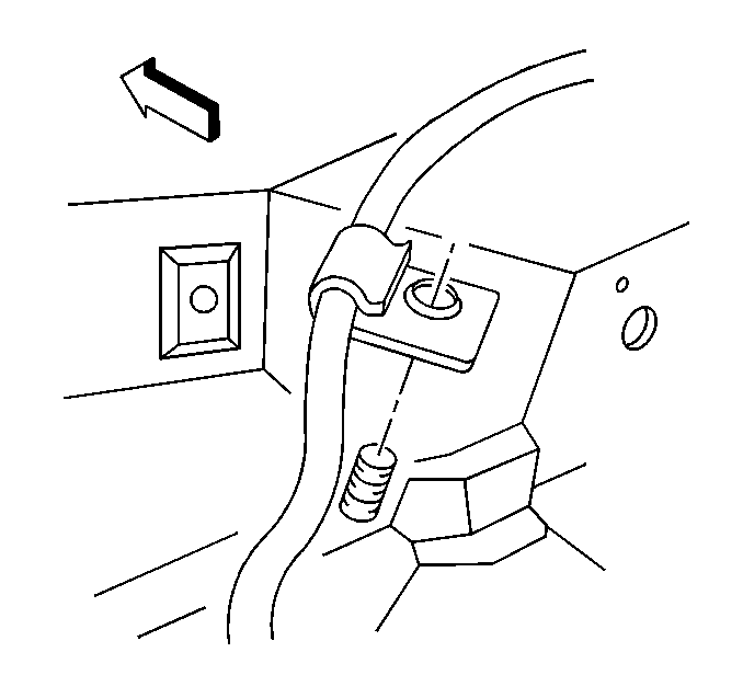
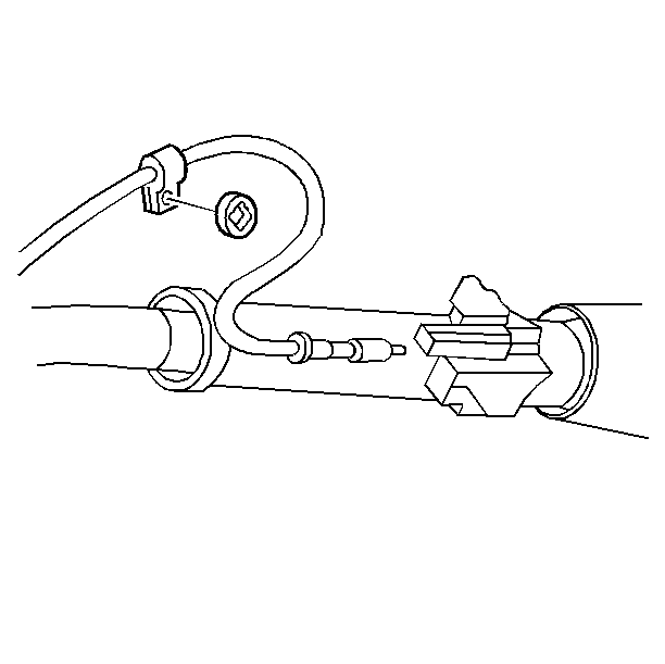
- Remove the park/lock cable clip from the stud on the front of dash.
- Remove the park/lock cable from the bracket.
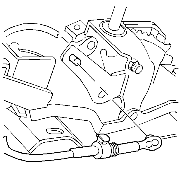
- Move the park/lock cable button to the UP position.
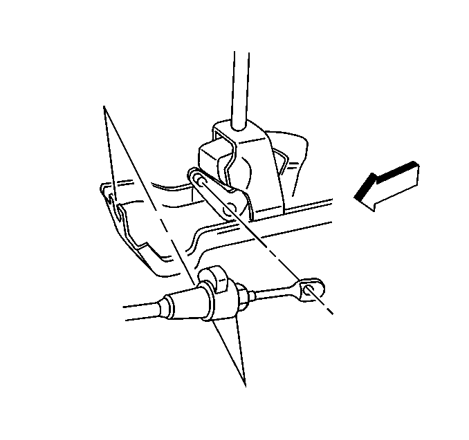
- Unsnap the cable terminal from the park/lock lever pin.
- Lower the steering column. Refer to Steering Wheel and Column.
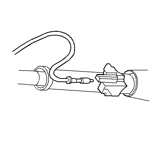
- Unsnap the park/lock cable from the steering column.
Important: Do not proceed to the next step with the ignition key in any other position.
Installation Procedure
- Place the automatic transmission control in the PARK position.
- Turn the ignition key to the RUN position.
- Snap the cable terminal to the park/lock lever pin.
- Push the park/lock cable connector forward in order to remove slack.
- With no load applied to the connector, press the park/lock cable lock button down.
- Install the park/lock cable to the bracket. Complete the following steps:
- Push the park/lock cable button down.
- Snap the park/lock cable into the steering column.
- Raise the steering column. Refer to Steering Wheel and Column.
- Install the park/lock clip to the stud on the front of dash.
- Install the front floor console. Refer to Instrument Panel, Gauges, and Console.
- Install the instrument panel driver knee bolster deflector. Refer to Instrument Panel, Gauges, and Console.
- Install the instrument panel driver knee bolster. Refer to Instrument Panel, Gauges, and Console.
- Install the LH instrument panel insulator. Refer to Instrument Panel, Gauges, and Console.
- Turn the ignition key to the OFF position.
- Connect the negative battery cable.
- Enable the SIR system. Refer to SIR System.
Important: Do not proceed to the next step with the ignition key in any other position.

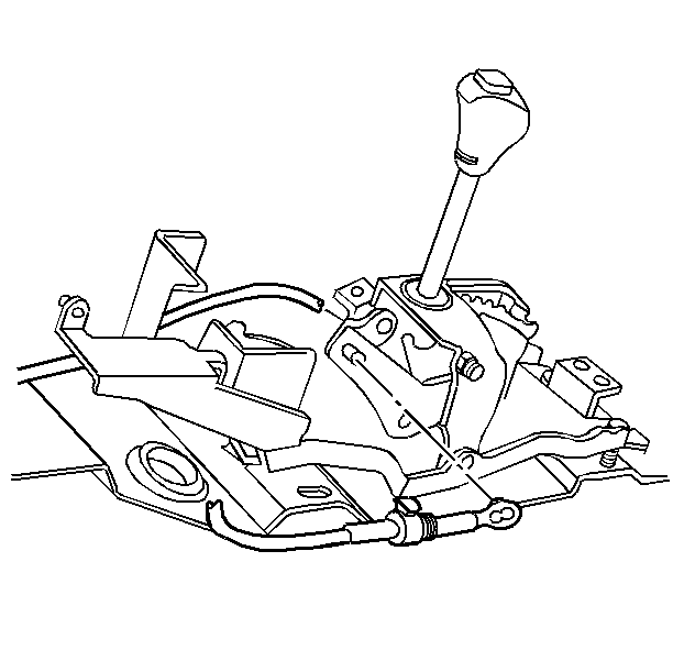
| 6.1. | Push the bracket housing against the adjusting spring. |
| 6.2. | Drop the park/lock cable through the slot in the bracket and seat the cable to the automatic transmission control. |


Tighten
Negative battery cable to 15 N·m(11 lb ft).
Inspection Procedure
Inspect the cable for functional operation. Complete the following procedure:
- Place the shift lever in Park. Place the key in the LOCK position. Ensure that you cannot move the shifter lever to another position. The ignition key should be removable from the column.
- Place the key in the RUN position. Place the shift lever in Neutral. Ensure that you cannot turn the key to the LOCK position.
- If the above conditions are met, the system is properly adjusted. Go to step 5.
- If the above conditions are not met, move the button to the UP position, and readjust the cable. Then, push the button down and recheck operation.
- If you cannot remove the key in the Park position, move the button to the UP position. Then, move the cable connector nose rearward until the ignition key can be removed.
- Snap the button down.
- Reinstall the cable into the park/lock clip in order to ensure correct routing.
