Water Pump Replacement 3800 VIN K
Removal Procedure
- Drain the coolant from the radiator to a level below the thermostat. Refer to Cooling System Draining and Filling Draining and Filling Cooling System in Engine Cooling.
- Loosen the water pump pulley bolts.
- Remove the serpentine drive belt. Refer to Drive Belt Replacement in Engine Mechanical.
- Remove the radiator inlet hose from the water pump.
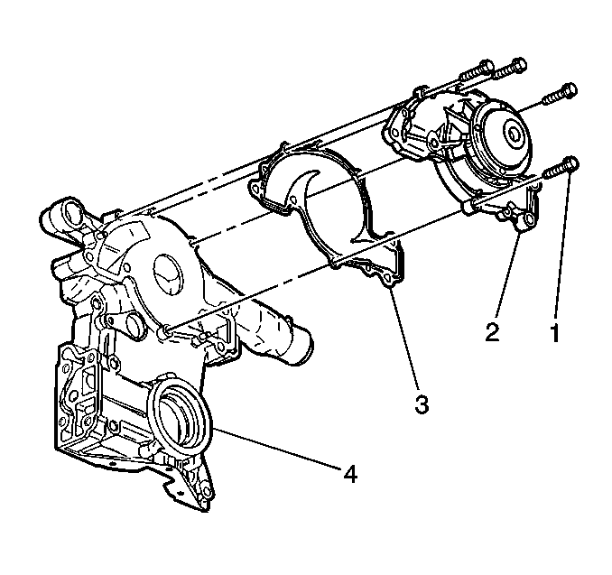
- Remove the water pump pulley bolts (6).
- Remove the water pump pulley (7).
- Remove the water pump bolts (5).
- Remove the water pump (4).
- Remove the water pump gasket (1).
- Clean all of the gasket mating surfaces, including the water pump bolts.

Installation Procedure
Tools Required
J 36660-A Torque Angle Meter
- Install a new water pump gasket (1).
- Install the water pump (4).
- Install the water pump bolts (5).
- Connect the radiator inlet hose to the water pump.
- Install the water pump pulley (7) and the bolts (6).
- Install the serpentine drive belt. Refer to Drive Belt Replacement in Engine Mechanical.
- Add the engine coolant. Refer to Cooling System Draining and Filling Draining and Filling Cooling System in Engine Cooling.
- Start the engine. After the engine reaches normal operating temperature, check for coolant leaks.

Tighten
Tighten the water pump bolts (5) to 15 N·m (11 lb ft
) plus an additional 80° using the J 36660-A
Torque Angle Meter
Notice: Use the correct fastener in the correct location. Replacement fasteners must be the correct part number for that application. Fasteners requiring replacement or fasteners requiring the use of thread locking compound or sealant are identified in the service procedure. Do not use paints, lubricants, or corrosion inhibitors on fasteners or fastener joint surfaces unless specified. These coatings affect fastener torque and joint clamping force and may damage the fastener. Use the correct tightening sequence and specifications when installing fasteners in order to avoid damage to parts and systems.
Tighten
Tighten the water pump pulley bolts (6) to 13 N·m (115 lb in).
Water Pump Replacement 5.7L VIN P
Removal Procedure
- Raise the vehicle. Support the vehicle. Refer to General Vehicle Lifting and Jacking in General Information.
- Disconnect the electrical connectors from the electric engine coolant fan.
- Remove the electric engine cooling fans. Refer to Electric Cooling Fan .
- Remove the engine block coolant drain hole plug and the knock sensor.
- Drain the cooling system. Refer to Cooling System Draining and Filling .
- Install the coolant drain hole drain plug and the knock sensor.
- Tighten the knock sensor to 19N·m (14 lb ft).
- Lower the vehicle.
- Remove the Intake Air Temperature (IAT) sensor electrical connector.
- Remove the air intake duct from the throttle body and Mass Airflow (MAF) sensor.
- Remove the upper and lower radiator hoses from the water pump.
- Remove the heater hoses from the water pump and the throttle body. Refer to Heater and Ventilation.
- Disconnect the Engine Coolant Temperature (ECT) sensor electrical connector.
- Reposition the ignition coil and the bracket.
- Remove the air pump and the bracket. Refer to Engine Controls.
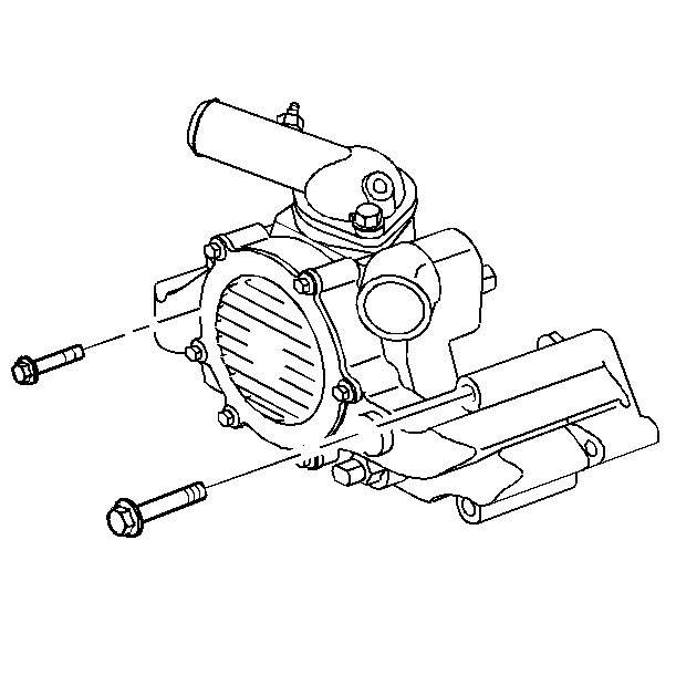
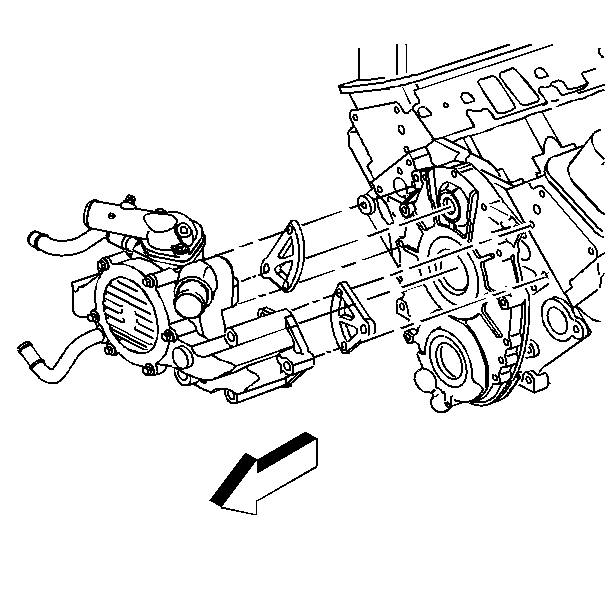
- Remove the water pump bolts and the stud.
- Remove the water pump from the vehicle.
- Remove the water pump gaskets.
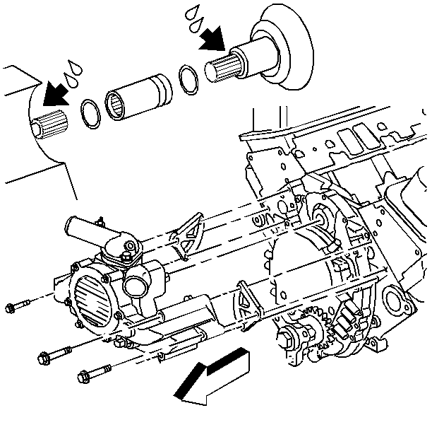
- Remove the driveshaft coupling, and the water pump driveshaft seals.
- Clean the water pump gasket surfaces.
- Clean the water pump bolts and the stud.
Tighten
Tighten the coolant drain hole plug to 18 N·m (13
lb ft).
Notice: Use the correct fastener in the correct location. Replacement fasteners must be the correct part number for that application. Fasteners requiring replacement or fasteners requiring the use of thread locking compound or sealant are identified in the service procedure. Do not use paints, lubricants, or corrosion inhibitors on fasteners or fastener joint surfaces unless specified. These coatings affect fastener torque and joint clamping force and may damage the fastener. Use the correct tightening sequence and specifications when installing fasteners in order to avoid damage to parts and systems.


Installation Procedure
Tools Required
J 41546 Water Pump Driven Gear Assembly Installer
- Install the water pump driveshaft coupling, with the groove toward the engine, and the driveshaft seals using the J 41546 .
- Install the water pump gaskets.
- Install the water pump.
- Install the water pump bolts and the stud.
- Install the air pump and the bracket. Refer to Engine Controls.
- Position the coil and the bracket.
- Install the electrical connector to the coolant sensor.
- Connect the heater hoses to the water pump and the throttle body. Refer to Heater and Ventilation.
- Install the upper and lower radiator hoses to the water pump.
- Install the air intake duct to the throttle body and Mass Airflow (MAF) sensor.
- Install the Intake Air Temperature (IAT) sensor electrical connector.
- Install the electric engine coolant fans. Connect the electrical connectors to the electric engine coolant fans. Refer to Electric Cooling Fan .
- Refill the cooling system. Refer to Cooling System Draining and Filling .
- Start and run the engine. After the engine reaches normal operating temperature, check for coolant leaks.
Important: Before assembling the drive coupling, apply a light coat of chassis grease to the seals and the splines.


Tighten
Tighten the bolts and the stud to 45 N·m (33 lb ft).
Notice: Use the correct fastener in the correct location. Replacement fasteners must be the correct part number for that application. Fasteners requiring replacement or fasteners requiring the use of thread locking compound or sealant are identified in the service procedure. Do not use paints, lubricants, or corrosion inhibitors on fasteners or fastener joint surfaces unless specified. These coatings affect fastener torque and joint clamping force and may damage the fastener. Use the correct tightening sequence and specifications when installing fasteners in order to avoid damage to parts and systems.
