For 1990-2009 cars only
Valve Rocker Arm Cover Replacement Right Side
Removal Procedure
- Disconnect the negative battery cable.
- Raise and suitably support the vehicle. Refer to SECTION 0A.
- Remove the accessory drive belt. Refer to Drive Belt Replacement .
- Remove the automatic transmission fluid level indicator tube bolt from the transmission housing, if equipped. Refer to SECTION 7A.
- Lower the vehicle.
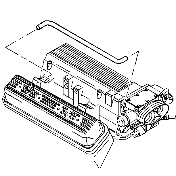
- Remove the crankcase vent hose.
- Remove the generator and the rear generator brace. Refer to SECTION 6D3.
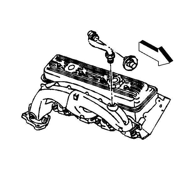
- Remove the secondary air injection pipe from the exhaust manifold.
- Remove the valve rocker arm cover bolts.
- Remove the valve rocker arm cover and the gasket.
- Clean the valve rocker arm cover and the cylinder head gasket surfaces.


Installation Procedure
- Install the valve rocker arm cover and gasket.
- Install the valve rocker arm cover bolts.
- Install the secondary air injection pipe to the exhaust manifold.
- Install the generator and the rear generator brace. Refer to SECTION 6D3.
- Install the crankcase vent hose.
- Raise and suitably support the vehicle. Refer to SECTION 0A.
- Install the transmission fluid level indicator tube bolt to the transmission housing, if removed.
- Install the accessory drive belt. Refer to Drive Belt Replacement .
- Lower the vehicle.
- Connect the negative battery cable.

Tighten
Tighten the valve rocker arm cover bolts to 12 N·m (106 lb in).

Tighten
Tighten the secondary air injection pipe to 55 N·m (47 lb ft).

Valve Rocker Arm Cover Replacement Left Side
Removal Procedure
- Disconnect the negative battery cable.
- Remove the brake booster vacuum hose.
- Remove the secondary air injection hose from the pump to the check valve.
- Remove the secondary air injector pipe from the exhaust manifold.
- Remove the accelerator control/cruise control servo cable adjuster, if equipped. Refer to SECTION 5E2.
- Remove the valve rocker arm cover bolts.
- Remove the valve rocker arm cover and gasket.
- Clean the valve rocker arm cover and the cylinder head gasket surfaces.


Installation Procedure
- Install the valve rocker arm cover and gasket.
- Install the valve rocker arm cover bolts.
- Install the accelerator control/cruise control servo cable adjuster, if equipped. Refer to SECTION 5E2.
- Install the secondary air injection pipe to the exhaust manifold.
- Install the secondary air injection hose to the pump and the check valve.
- Install the brake booster vacuum hose.
- Connect the negative battery cable.

Tighten
Tighten the valve rocker arm cover bolts to 12 N·m (106 lb in).

Tighten
Tighten the secondary air injection pipe to the exhaust manifold to
55 N·m (47 lb ft).
