Removal Procedure
Tools Required
| • | J 41044 Engine Support Adapters |
| • | J 42451 Engine Support Adapter Kit |
| • | J 28467-B Universal Support Fixture |
| • | J 36462-A Engine Support Adapter Leg |
Important: DO NOT reuse the oil pan gasket. The original oil pan gasket is retained and aligned to the oil pan by rivets. When installing a new gasket, it is not necessary to rivet the gasket to the oil pan.
- Support the engine using the J 41044 , J 42451 , J 28467-B and J 36462-A .
- Disconnect the front brake pipes from the brake pressure modulator valve (BPMV).
- Plug or cap the brake pipes and BPMV to prevent contamination.
- Remove the starter motor. Refer to Starter Motor Replacement in Engine Electrical.
- Remove the oil drain plug.
- Drain the engine oil.
- Remove the oil filter.
- Remove the right side engine mount to cradle bolts.
- Remove the left side engine mount to cradle bolts.
- Remove the right and left end link nuts (7).
- Remove the right and left end links (3) and sleeves (5).
- Remove the left and right side shock absorber lower mounting bolts.
- Remove the intermediate steering shaft bolt.
- Position the steering shaft out of the way.
- Remove the power steering gear nuts (4) and bolts (1).
- Separate the gear from the crossmember and support.
- Disconnect the left and right side wheel speed sensor electrical connectors.
- If necessary, disconnect the heated oxygen sensor (HO2S) electrical connectors.
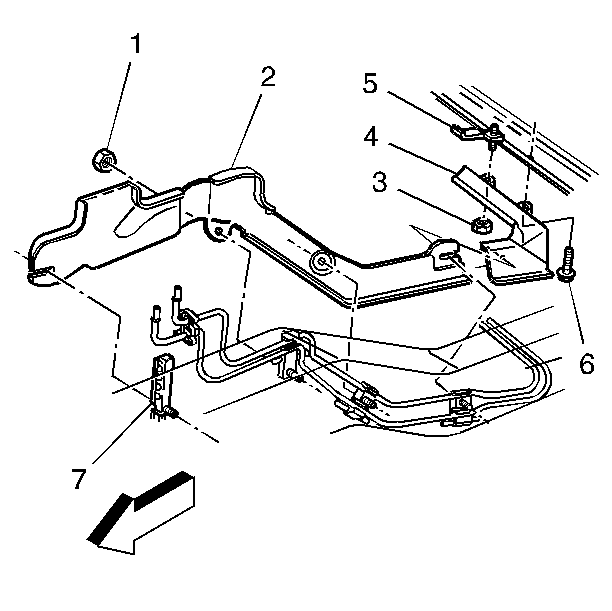
- Remove the front fuel pipe heat shield nuts (1).
- Remove the front fuel pipe heat shield (2).
- Remove the front brake pipes from the retaining clip.
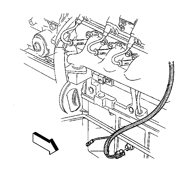
- Disconnect the oil level sensor connector, if required.
- Remove the oil level sensor from the oil pan, if required.
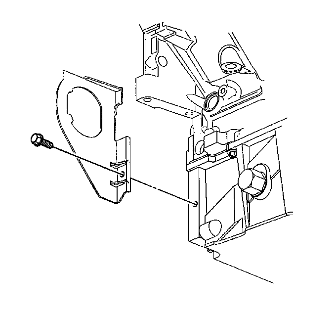
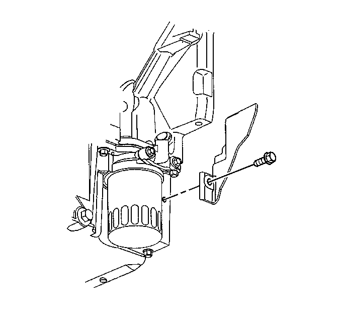
- Remove the right side closeout and bolt.
- Remove the left side closeout and bolt.
- Support the crossmember with a suitable jack.
- Remove the crossmember bolts.
- Lower the crossmember.
- Remove the bottom two transmission bellhousing bolts.
- Remove the oil pan bolts (1).
- Rotate the oil pan until it can be removed from around the oil pump screen.
- Drill out the oil pan gasket rivet (2), if necessary.
- Discard the old gasket and rivet.





Important: Use care not to gouge, score, or damage the oil pan sealing surface.
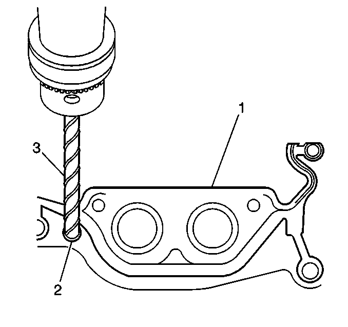
Important: DO NOT allow foreign material to enter the oil passages of the oil pan, cap or cover the openings as required.
Installation Procedure
Important: The alignment of the structural oil pan is critical. The rear bolt hole locations of the oil pan provide mounting points for the transmission bellhousing. To ensure the rigidity of the powertrain and correct transmission alignment, it is important that the rear of the block and the rear of the oil pan must NEVER protrude beyond the engine block and transmission bellhousing plane.
- Apply a 5 mm (0.2 in) bead of sealant GM P/N 12378190 or equivalent 20 mm (0.8 in) long to the engine block.
- Apply the sealant directly onto the tabs of the front cover gasket that protrudes into the oil pan surface.
- Apply a 5 mm (0.2 in) bead of sealant GM P/N 12378190 or equivalent 20 mm (0.8 in) long to the engine block.
- Apply the sealant directly onto the tabs of the rear cover gasket that protrudes into the oil pan surface.
- Pre-assemble the oil pan gasket to the pan (2).
- Install the oil pan (2), gasket and bolts (1) to the engine block.
- Snug the oil pan bolts (1) finger tight. Do not overtighten.
- Install the two lower bellhousing bolts to position the oil pan correctly.
- Snug the lower bellhousing bolt finger tight. Do not overtighten.
- Tighten the oil pan-to-block and oil pan-to-oil pan front cover bolts to 25 N·m (18 lb ft).
- Tighten the oil pan-to-rear cover bolts to 12 N·m (106 lb in).
- Tighten the bellhousing bolts to 50 N·m (37 lb ft).
- Raise the crossmember.
- Install the crossmember bolts.
- Install the left side closeout and bolt.
- Install the right side closeout and bolt.
- Install the oil level sensor to the oil pan, if removed.
- Connect the oil level sensor electrical connector.
- Install the front brake pipes to the retaining clip.
- Install the front fuel pipe heat shield (2).
- Install the front fuel pipe heat shield nuts (1).
- If necessary, connect the HO2S electrical connectors.
- Connect the left and right wheel speed sensor electrical connectors.
- Position the gear to the crossmember.
- Install the power steering gear bolts (1) and nuts (4).
- Position the steering shaft to the gear.
- Install the intermediate steering shaft and bolt.
- Install the left and right side shock absorber lower mounting bolts.
- Install the right and left sleeves (5) and end links (3).
- Install the right and left end link nuts (7).
- Install the left side engine mount to cradle bolts.
- Install the right side engine mount to cradle bolts.
- Install the oil filter.
- Install the oil drain plug.
- Install the starter motor. Refer to Starter Motor Replacement in Engine Electrical.
- Lower the vehicle.
- Remove the caps or plugs from the brake pipes and BPMV.
- Connect the brake pipes to the BPMV.
- Remove the J 41044 , J 42451 , J 28467-B and J 36462-A .
- Bleed the brakes. Refer to Hydraulic Brake System Bleeding in Hydraulic Brakes.
- Refill the engine with oil.
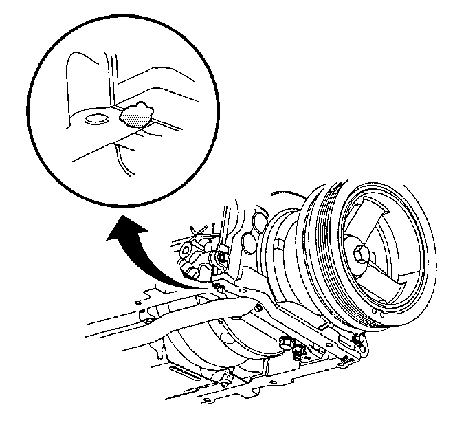
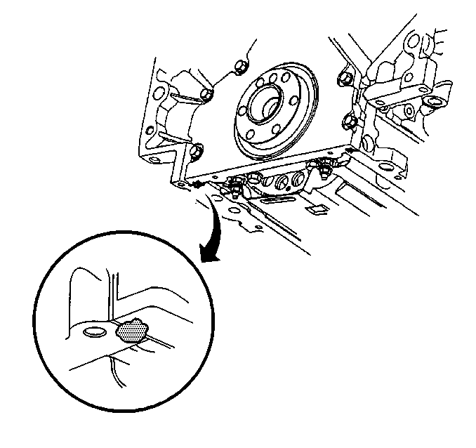

| • | Install the gasket onto the pan (2). |
| • | Install the oil pan bolts (1) to the pan through the gasket. |
Notice: Use the correct fastener in the correct location. Replacement fasteners must be the correct part number for that application. Fasteners requiring replacement or fasteners requiring the use of thread locking compound or sealant are identified in the service procedure. Do not use paints, lubricants, or corrosion inhibitors on fasteners or fastener joint surfaces unless specified. These coatings affect fastener torque and joint clamping force and may damage the fastener. Use the correct tightening sequence and specifications when installing fasteners in order to avoid damage to parts and systems.
Tighten

Tighten
| • | Tighten the upper four cradle bolts to 125 N·m (92 lb ft). |
| • | Tighten the lower two cradle bolts to 145 N·m (107 lb ft). |

Tighten
Tighten the left side closeout bolt to 12 N·m (106 lb in).

Tighten
Tighten the right closeout bolt to 12 N·m (106 lb in).

Tighten
Tighten the oil level sensor to 13 N·m (115 lb in).


Tighten
Tighten the front fuel pipe heat shield nuts to 5 N·m (44 lb in).


Tighten
Tighten the power steering gear bolts to 85 N·m (63 lb ft).

Tighten
Tighten the intermediate shaft bolt to 47 N·m (35 lb ft).

Tighten
Tighten the shock absorber bolts to 65 N·m (48 lb ft).

Tighten
Tighten the end link nuts to 23 N·m (17 lb ft).

Tighten
Tighten the engine mount to cradle bolts to 58 N·m (43 lb ft).

Tighten
Tighten the right side engine mount cradle bolts to 58 N·m
(43 lb ft).

Tighten
Tighten the oil filter to 30 N·m (22 lb ft).
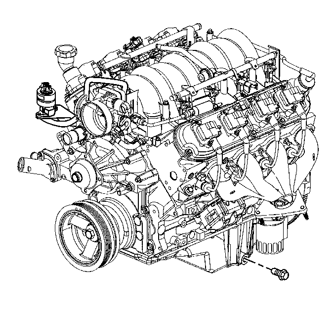
Tighten
Tighten the oil drain plug to 25 N·m (18 lb ft).
Tighten
Tighten the brake pipe fittings to 15 N·m (11 lb ft).
