For 1990-2009 cars only
Removal Procedure
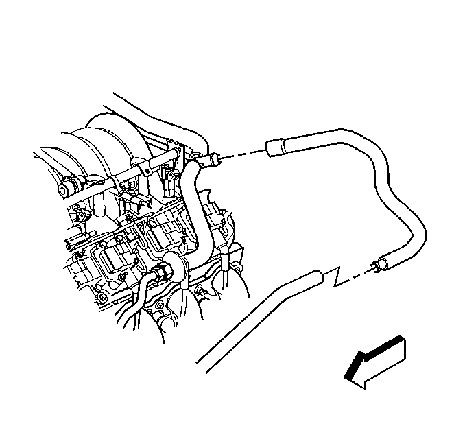
- Disconnect the secondary air injection (AIR) pump hose from the check valve hose.
- Remove the AIR valve hose clamps and hose.
- Remove the AIR pipe (with check valve ), bolts and gasket from the right exhaust manifold.
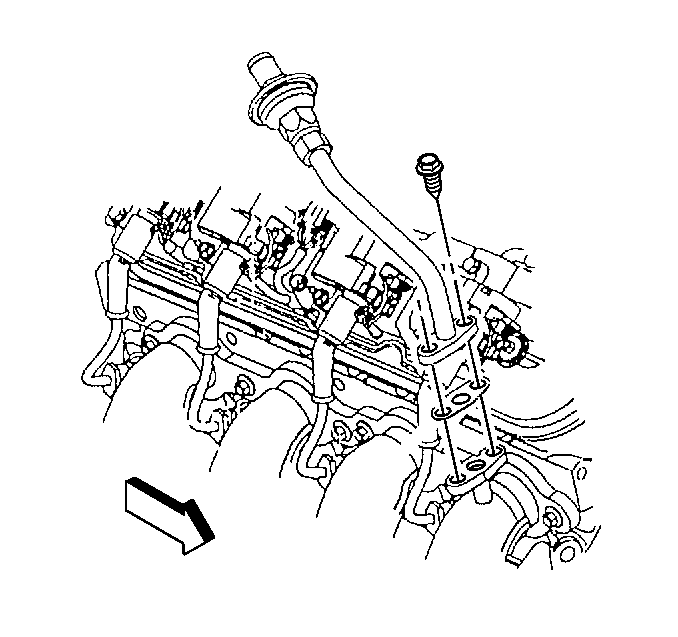
- Remove the number 4 and 6 spark plug wires.
- Remove the number 4 and 6 ignition coils from the coil bracket.
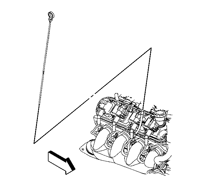
- Remove the oil level indicator from the tube.
- Remove the oil level indicator tube bolt.
- Remove the indicator tube from the engine block.
- Remove the O-ring from the tube.


Installation Procedure
- Clean the indicator tube.
- Install a new O-ring to the tube.
- Install the oil level indicator tube.
- Rotate the tube into the proper position.
- Install the oil level indicator tube bolt.
- Install the indicator to the tube.
- Install the number 4 and 6 ignition coils to the coil bracket.
- Install the number 4 and 6 spark plug wires.
- Install the AIR pipe (with check valve ), bolts and gasket from the right exhaust manifold.
- Install the AIR valve hose and clamps.
- Connect the AIR pump hose to the check valve hose.

Tighten
Tighten the oil level indicator tube bracket bolt to 25 N·m
(18 lb ft).


Tighten
Tighten the ignition coil bolts to 12 N·m (106 lb in).

Tighten
Tighten the AIR pipe to exhaust manifold bolts th 20 N·m
(15 lb ft).


