Removal Procedure
Tools Required
J 8614-01 Pinion Flange
Remover and Installer
- Raise and suitably support the vehicle. Refer to
Lifting and Jacking the Vehicle
in General Information.
- Remove the propeller shaft. Refer to
One-Piece Propeller Shaft Replacement
or
Two-Piece Propeller Shaft Replacement
in Propeller Shaft.

- Mark the position of the
following components before disassembly:
| • | The drive pinion gear yoke (1) |
| • | The drive pinion gear nut |
| • | This action will ensure that the correct drive pinion gear inner and
outer bearing preload can be maintained. |

- Use J 8614-01
in order to remove the following components:
| • | The drive pinion gear nut |
| • | The drive pinion gear washer |
- Use a suitable container in order to hold any fluid that may drain
from the rear axle.

- Use J 8614-01
in order to remove the drive pinion
gear yoke (1).

Important: Do not damage the rear axle housing when removing the drive pinion gear
seal.
- Use a blunt chisel in order to drive the drive pinion gear seal (1)
out of the rear axle housing.
- Inspect the drive pinion gear seal (1) surface of the drive
pinion gear yoke for the following conditions:
| • | Damage, such as a groove worn by the drive pinion gear seal. |
- If the drive pinion gear yoke is damaged, replace the drive pinion
gear yoke.
- Inspect the housing bore for burrs.
Burrs might cause leaks around the outer diameter (OD) of the drive
pinion gear seal (1).
Remove any burrs that might cause leaks around the outer diameter (OD)
of the drive pinion gear seal (1).
Installation Procedure
Tools Required
| • | J 8614-01 Pinion
Flange Remover and Installer |
| • | J 23911 Pinion
Oil Seal Installer |

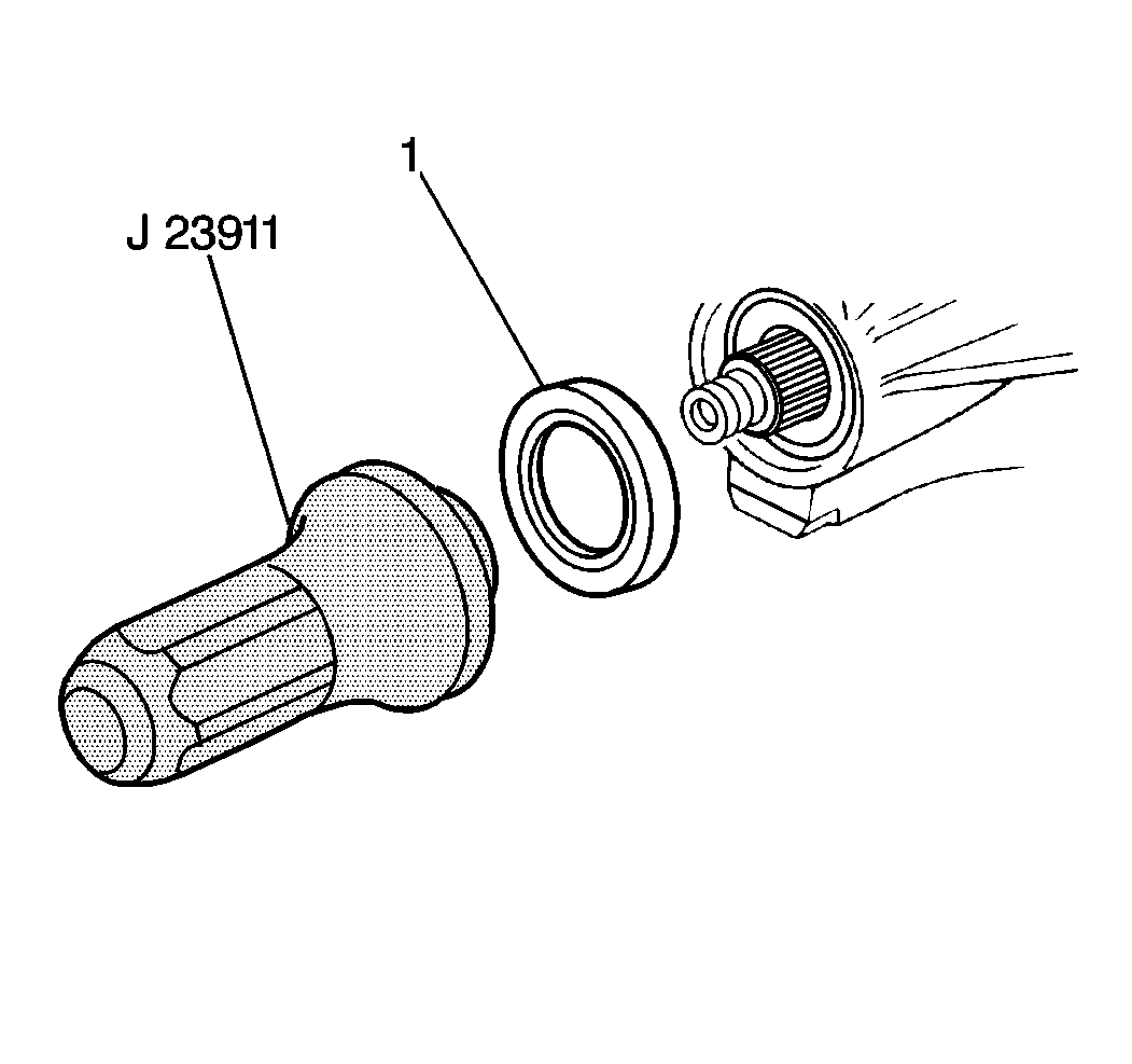
- Use the J 23911
in order to install a new drive pinion
gear seal (1).
- Apply chassis lubricant or an equivalent to the following components:
| • | The outside diameter of the drive pinion gear yoke |
| • | The sealing lip of the new drive pinion gear seal (1) |

- Install the drive pinion
gear yoke (1).
- Install the following components:
| • | The drive pinion gear washer |
| • | The drive pinion gear nut |
| • | Finger tighten the drive pinion gear nut. |

Notice: Use the correct fastener in the correct location. Replacement fasteners
must be the correct part number for that application. Fasteners requiring
replacement or fasteners requiring the use of thread locking compound or sealant
are identified in the service procedure. Do not use paints, lubricants, or
corrosion inhibitors on fasteners or fastener joint surfaces unless specified.
These coatings affect fastener torque and joint clamping force and may damage
the fastener. Use the correct tightening sequence and specifications when
installing fasteners in order to avoid damage to parts and systems.
- Hold the drive pinion
gear yoke. Use J 8614-01
in
order to tighten the drive pinion gear nut to the position that was marked.
Tighten
Tighten the drive pinion gear nut to 1.59 mm (1/16 inch)
beyond the alignment mark.
- Install the propeller shaft. Refer to
One-Piece Propeller Shaft Replacement
or
Two-Piece Propeller Shaft Replacement
in Propeller Shaft.
- Measure the rear axle lubricant level and add lubricant, if necessary.
Refer to
Lubricant Level Check
.
- Lower the vehicle.
- Inspect for correct operation of the rear axle.


