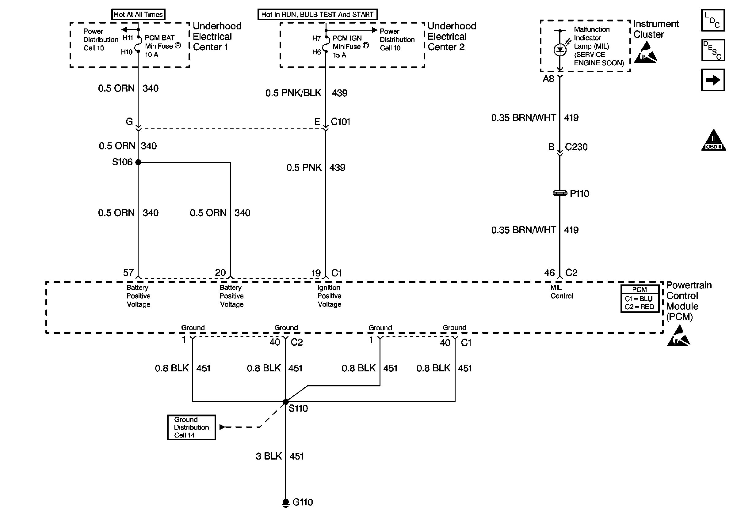
Refer to
Power, Ground and MIL

for complete circuit details.
Circuit Description
The PCM continuously monitors the system voltage. The system voltage information is taken from the PCM's ignition feed circuits. Voltages below 8.0 volts or above 18.0 volts causes improper system operation and/or component damage. The PCM operates in a default mode if a PCM voltage DTC sets. The PCM disables most outputs to protect the hardware if the system voltage is high. A scan tool may not display data if system voltage is below 8.0 volts. Use a DMM to monitor the system voltage in order to verify if the fault is currently present. A low voltage may cause a stalling condition, or other driveability concerns.
Conditions for Running the DTC
| • | The engine run time is longer than 10 seconds. |
| • | The engine speed is greater than 1,000 RPM. |
| • | The vehicle speed is greater than 8 km/h (5 mph). |
Conditions for Setting the DTC
| • | The PCM senses system voltage below 8.0 volts. |
| • | All the above conditions are present for 5 seconds. |
Action Taken When the DTC Sets
| • | The PCM stores DTC P0562 in memory when the diagnostic runs and fails. |
| • | The Malfunction Indicator Lamp (MIL) will not illuminate. |
| • | The PCM will record the operating conditions at the time the diagnostic fails. The PCM stores this information in Failure Records. |
| • | The PCM will command a high idle speed. |
| • | The transmission defaults to third gear. |
| • | The TCC operation is inhibited. |
Conditions for Clearing the DTC
| • | A last test failed, or current DTC, clears when the diagnostic runs and does not fail. |
| • | A history DTC will clear after 40 consecutive warm-up cycles, if no failures are reported by this or any other non-emission related diagnostic. |
| • | Use a scan tool in order to clear the DTC. |
Diagnostic Aids
Important:
• Remove any debris from the PCM connector surfaces before servicing
the PCM. Inspect the PCM connector gaskets when diagnosing/replacing
the PCM. Ensure that the gaskets are installed correctly. The gaskets
prevent contaminate intrusion into the PCM. • For any test that requires probing the PCM or a component
harness connector, use the Connector Test Adapter Kit J 35616
. Using this kit prevents damage
to the harness/component terminals. Refer to
Using Connector Test Adapters
in Wiring Systems.
| • | The following may cause an intermittent: |
| - | Poor connections; Refer to Intermittents and Poor Connections Diagnosis in Wiring Systems. |
| - | Corrosion |
| - | Mis-routed harness |
| - | Rubbed through wire insulation |
| - | Broken wire inside the insulation |
| • | An extremely low voltage (below 7.5 volts) may cause the loss of serial data and the MIL may not function. An open ignition feed circuit causes a no start and the MIL will not illuminate. A low system voltage may cause other DTCs to set. |
| • | Using Freeze Frame and/or Failure Records data may aid in locating an intermittent condition. If you cannot duplicate the DTC, the information included in the Freeze Frame and/or Failure Records data can aid in determining how many miles since the DTC set. The Fail Counter and Pass Counter can also aid determining how many ignition cycles the diagnostic reported a pass and/or a fail. Operate the vehicle within the same freeze frame conditions (RPM, load, vehicle speed, temperature etc.) that you observed. This will isolate when the DTC failed. |
| • | For an intermittent condition, refer to Symptoms . |
Test Description
The numbers below refer to the step numbers on the diagnostic table.
Step | Action | Value(s) | Yes | No |
|---|---|---|---|---|
1 | Did you perform the Powertrain On-Board Diagnostic (OBD) System Check? | -- | ||
|
Important: If DTC P1637 is also set, refer to DTC P1637 Generator L-Terminal Circuit for further diagnosis. Ensure the Battery is fully charged before proceeding with this diagnostic. Monitor the Ignition 1 Voltage using the scan tool. Does the scan tool display the specified value? | B+ | Go to Charging System Check in Engine Electrical | ||
3 | Inspect the PCM IGN fuse Is the fuse open? | -- | ||
4 |
Is the voltage at the specified value? | B+ | ||
5 | Test the continuity of the Ignition feed circuit using the DMM J 39200 . Refer to Testing for Continuity in Wiring Systems. Does the DMM display continuity below the specified value? | 5ohms | ||
6 |
Is the action complete? | -- | -- | |
7 |
Did you find and correct the condition? | -- | ||
8 |
Important:: Program the replacement PCM. Refer to Powertrain Control Module Replacement/Programming . Replace the PCM. Is the action complete? | -- | -- | |
9 |
Does the scan tool indicate that this test ran and passed? | -- | ||
10 | Select the Capture Info option and the Review Info option using the scan tool. Does the scan tool display any DTCs that you have not diagnosed? | -- | Go to the applicable DTC table | System OK |
