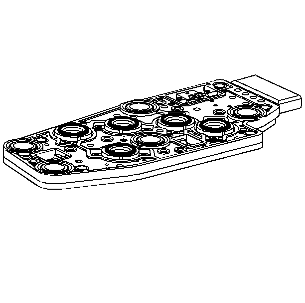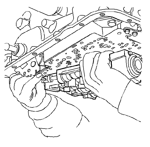
- Install the control valve
body to the transmission case and connect the manual valve link to the inside
detent lever.
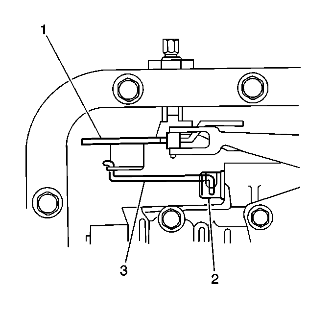
- Verify that the manual
valve link (3) is installed properly to the inside detent lever (1) and the
manual valve (2).
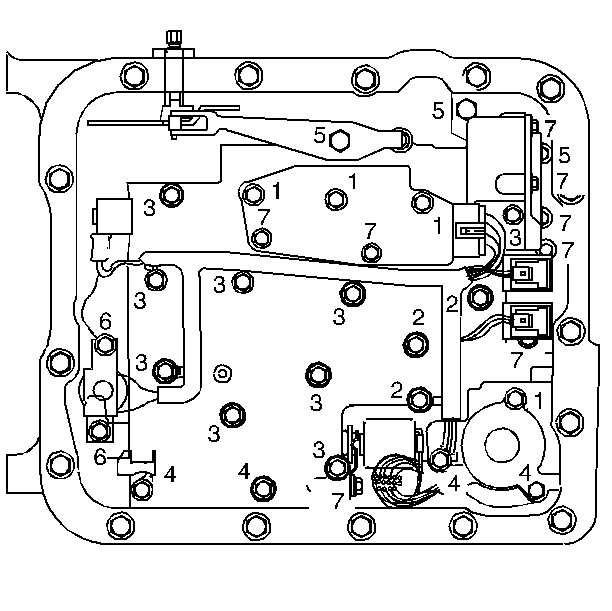
Important: When installing bolts throughout this procedure, be sure to use the
correct bolt size and length in the correct location as specified.
- Install but do not tighten the control valve body bolts which retain
only the valve body directly.
Each numbered bolt location corresponds to a specific bolt size and
length, as indicated by the following:
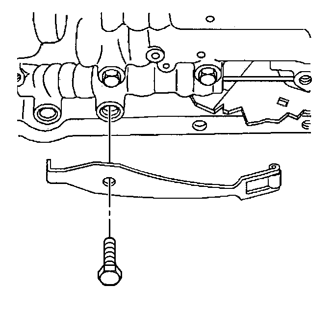
- Install the manual detent
spring.
- Install but do not tighten the manual detent spring retaining
bolt.
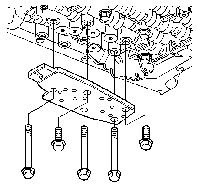
- Install the transmission
fluid pressure switch.
- Install but do not tighten the control valve body bolts which
retain the transmission fluid pressure switch to the control valve body.
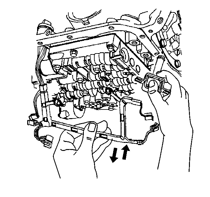
- Install the wiring harness
and TCC solenoid with a new O-ring seal to the valve body.
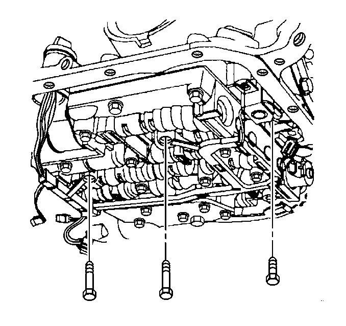
- Install but do not tighten
the valve body bolts which retain the internal wiring harness.
- Install the TCC solenoid retaining bolts.
Tighten
Tighten the TCC solenoid retaining bolts to 11 N·m (97 lb in).
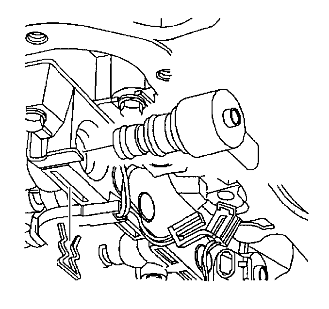
- Install the TCC PWM solenoid
to the control valve body.
- Install the TCC PWM solenoid retainer.
Notice: Torque valve body bolts in a spiral pattern starting from the center.
If the bolts are torqued at random, valve bores may be distorted and inhibit
valve operation.
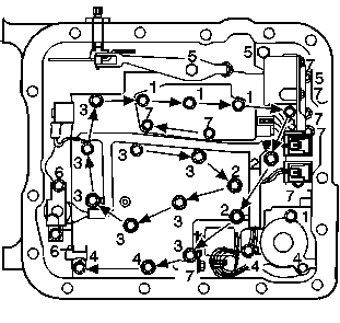
- Tighten the control valve
body bolts in a spiral pattern starting from the center, as indicated by the
arrows.
Tighten
Tighten the control valve body bolts (in sequence) to 11 N·m
(97 lb in).
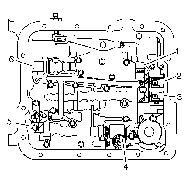
- Connect the internal wiring harness electrical connectors to the following
components:
| • | Transmission fluid pressure switch (1) |
| • | 1-2 shift control solenoid (2) |
| • | 2-3 shift control solenoid (3) |
| • | Pressure control solenoid (4) |
| • | 3-2 control solenoid (6) |
- Install the transmission oil pan and filter. Refer to
Automatic Transmission Fluid and Filter Replacement
.


