Removal Procedure
Tools Required
Notice: When raising or supporting the engine for any reason, do not use a jack
under the oil pan, crankshaft balancer, or any sheet metal. Due to small clearances
between the oil pan and the oil pump screen, jacking against the oil pan may
cause it to be bent against the pump screen, resulting in a damaged oil pickup
unit. Jacking against the crankshaft balancer may also cause oil seal and/or
crankshaft bearing damage. Always use a J 28467-A (Universal
Support Fixture) along with J 41044 (Engine Support Adapters) when raising
or supporting the engine.
- Remove the generator.
Refer to
Generator Replacement
in Engine Electrical.
- Remove the ignition control module. Refer to
Ignition Coil and Ignition Coil Module Replacement
in Engine Electrical.
- Raise and suitably support the vehicle. Refer to
Lifting and Jacking the Vehicle
in General Information.
- Remove the 3-way catalytic converter. Refer to
Catalytic Converter Replacement
in Engine Exhaust.
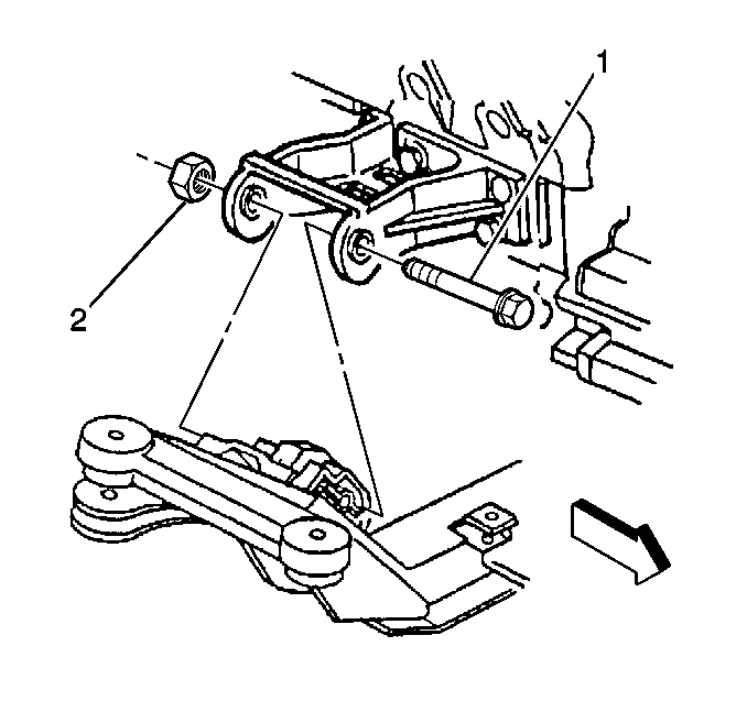
- Remove the right side engine mount through bolt nut (2).
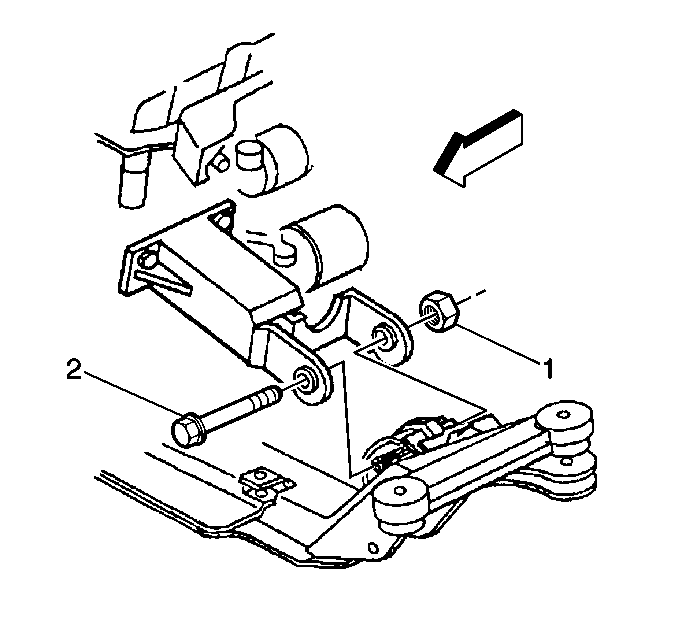
- Remove the left side engine
mount through bolt nut (1).
- Install the J 28467-360
and the J 41044
. Do this in order to remove the through bolt.
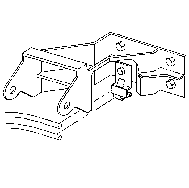
- Remove the transmission oil cooler pipe
bracket bolt and bracket.
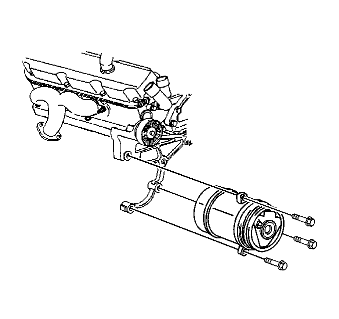
- Remove the air conditioning compressor
bolts.
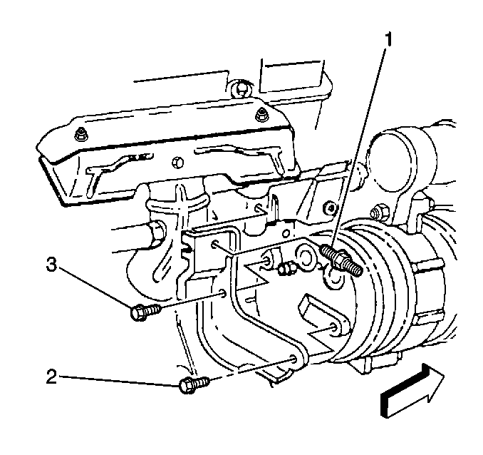
- Remove the air conditioning compressor
rear bolts (2, 3).
- Position the A/C compressor forward from the bracket.
Do this in order to remove the engine mount through bolt(s) without
recovering the refrigerant.
- Install the J 28467-90
to the strut tower bolts.
- Install the J 28467-A
and the J 41044
to the engine.
- Raise the engine using the J 28467-A
slightly to relieve tension on the through bolts.

- Remove the right engine
mount through bolt (1).

- Remove the left engine
mount through bolt (2).
- Raise the engine enough to remove the engine mounts and engine
mount brackets.
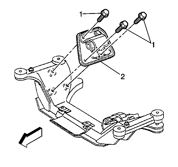
- Remove the right engine
mount bolts (1) and the right engine mount (2).
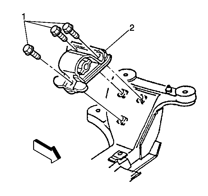
- Remove the left engine
mount bolts (1) and the left engine mount (2).

- Remove the right engine
mount bracket bolts (1, 2) and the right engine mount bracket (3).
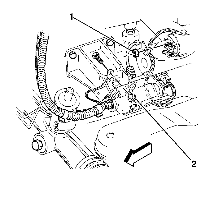
- Remove the positive cable from the engine
mount stud.
| • | Remove the battery positive cable nut (2). |
| • | Remove the harness clamp from the stud. |
| • | Remove the RF (Radio Frequency) ground strap. |

- Remove the left engine
mount bracket bolts (3).
- Remove the left engine mount bracket stud (2) and the engine mount
bracket (1).
- Visually Inspect the rubber portions of the engine mount for damage.
Installation Procedure

- Install the left engine mount bracket
(1) and stud (2) to the engine block.
- Install the left engine mount bracket bolts (3).
Tighten
| • | Tighten the engine mount bracket bolts (3) to 100 N·m
(74 lb ft). |
| • | Tighten the engine mount bracket stud (2) to 87 N·m
(64 lb ft). |

- Install the positive cable to the engine
mount bracket stud.
| • | Install the RF (Radio Frequency) ground strap. |
| • | Install the harness clamp to the stud. |
| • | Install the battery positive cable nut (2). |
Tighten
Tighten the battery positive cable nut (2) to 25 N·m (18 lb ft).

- Install the right engine
mount bracket (3) and bolts (1, 2) to the engine block.
Tighten
| • | Tighten the two engine mount bracket bolts (10 to 100 N·m
(74 lb ft). |
| • | Tighten the engine mount bracket bolt (2) to 50 N·m
(37 lb ft). |

- Install the left engine
mount (2) and bolts (1) to the crossmember.
Tighten
Tighten the left engine mount bolts (1) to 58 N·m (43 lb ft).

- Install the right engine
mount (2) and bolts (1) to the crossmember.
Tighten
Tighten the right engine mount bolts (2) to 58 N·m (43 lb ft).
- Lower the engine using the J 28467-A
until the mount bracket and mount through holes line up together.
- Remove the J 28467-A
and the J 41044
.
- Remove the J 28467-90
from the strut tower bolts.

- Install the left engine
mount through bolt (2).

- Install the right engine
mount through bolt (1).

- Position the A/C compressor rearward
to the bracket.
- Install the air conditioning compressor rear bolts (2, 3).
Tighten
Tighten the air conditioning compressor rear bolts (2, 3) to 30 N·m
(22 lb ft).

- Install the air conditioning compressor
bolts.
Tighten
Tighten the air conditioning compressor bolts to 50 N·m
(37 lb ft).

- Install the transmission oil cooler pipe
bracket and bolt.
Tighten
Tighten the oil cooler pipe bracket to 17 N·m (13 lb ft).

- Install the left side engine mount through
bolt nut (1).
Tighten
Tighten the engine mount through bolt nut (1) to 80 N·m
(59 lb ft).

- Install the right side engine mount through
bolt nut (2).
Tighten
Tighten the engine mount through bolt nut (2) to 80 N·m
(59 lb ft).
- Install the 3-way catalytic converter. Refer to
Catalytic Converter Replacement
in Engine Exhaust.
- Lower the vehicle.
- Install the ignition control module. Refer to
Ignition Coil and Ignition Coil Module Replacement
in Engine Electrical.
- Install the generator. Refer to
Generator Replacement
in Engine Electrical.


