Engine Mount Replacement Right
Removal Procedure
Tools Required
| • | J 42451 Engine
Support Adapter Kit |
Notice: When raising or supporting the engine for any reason, do not use a jack
under the oil pan, any sheet metal, or the crankshaft pulley. Due to the small
clearance between the oil pan and the oil pump screen, jacking against the
oil pan may cause the pan to be bent against the pump screen. This will result
in a damaged oil pickup unit.
- Support the engine using
the J 42451
, J 28467-B
, J 36462-A
and J 41044
.
- Raise and suitably support the vehicle. Refer to
Lifting and Jacking the Vehicle
in General Information.
- Remove the starter motor. Refer to
Starter Motor Replacement
in Engine Electrical.

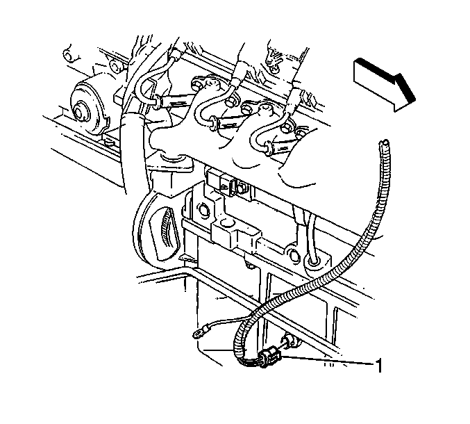
- Disconnect the oil level sensor electrical
connector (1).
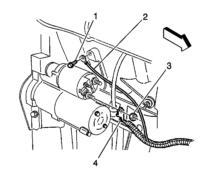
- Remove the negative battery
cable lead to engine block bolt (1).

- Remove the engine mount
bracket to crossmember bolts.
- Lower the vehicle.
- Raise the right side of the engine using the support fixture.
- Raise and suitably support the vehicle. Refer to
Lifting and Jacking the Vehicle
in General Information.

- Remove the engine mount
bracket bolts and bracket.
- Remove the engine mount from the vehicle.
- Separate the upper and lower mount on the bench.
Installation Procedure
- Loosely install the upper and lower mount together on the bench.
- Install the engine mount to the vehicle.

- Install the engine mount
bracket and bolts.
Tighten
Tighten the engine mount bracket to block bolts to 50 N·m
(37 lb ft).
- Lower the vehicle.
- Lower the right side of the engine.
- Raise and suitably support the vehicle. Refer to
Lifting and Jacking the Vehicle
in General Information.

- Install the engine mount
bracket to crossmember bolts.
Tighten
Tighten the engine mount bracket to crossmember bolts to 58 N·m
(43 lb ft).
- Tighten the engine mount through bolt and mount nut.
Tighten
| • | Tighten the engine mount through bolt to 95 N·m (70 lb ft). |
| • | Tighten the engine mount through bolt nut to 80 N·m
(59 lb ft). |

- Install the negative battery
cable lead to engine block bolt (1).
Tighten
Tighten the negative battery cable lead to engine block bolt (1) to
32 N·m (24 lb ft)

- Connect the oil level
sensor electrical connector (1).
- Install the starter motor. Refer to
Starter Motor Replacement
in Engine Electrical.
- Lower the vehicle.
Engine Mount Replacement Left
Removal Procedure
Tools Required
| • | J 42451 Engine
Support Adapter Kit |
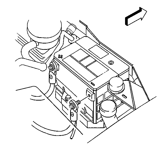
- Disconnect the negative
battery cable. Refer to
Battery Negative Cable Disconnection and Connection
in Engine Electrical.
Notice: When raising or supporting the engine for any reason, do not use a jack
under the oil pan, any sheet metal, or the crankshaft pulley. Due to the small
clearance between the oil pan and the oil pump screen, jacking against the
oil pan may cause the pan to be bent against the pump screen. This will result
in a damaged oil pickup unit.
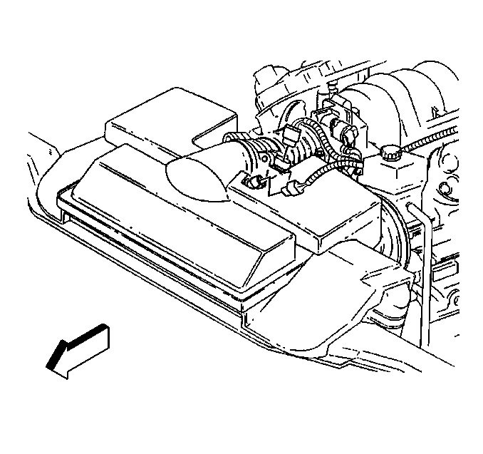
- Disconnect the intake
air temperature (IAT) sensor electrical connector.
- Disconnect the mass airflow (MAF) sensor electrical connector.
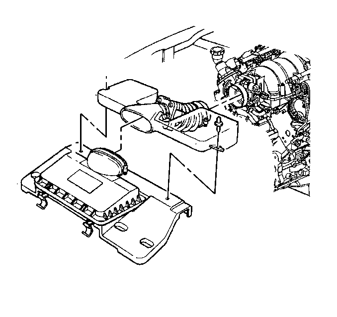
- Remove the air intake
duct from the throttle body and the air cleaner box.
- Support the engine using the J 42451
, J 28467-B
, J 36462-A
and J 41044
.
- Raise and suitably support the vehicle. Refer to
Lifting and Jacking the Vehicle
in General Information.
- Remove the left oxidation catalytic converter. Refer to
Oxidation Catalytic Converter Replacement
in Engine Exhaust.

- Remove the engine mount
bracket to crossmember bolts.
- Lower the vehicle.
- Raise the left side of the engine using the support fixture.
- Raise and suitably support the vehicle. Refer to
Lifting and Jacking the Vehicle
in General Information.

- Remove the engine mount
heat shield nuts.
- Remove the engine mount heat shield.

- Remove the engine mount
bracket to block studs.
- Remove the engine mount from the vehicle.
- Separate the upper and lower mount on the bench.
Installation Procedure
- Loosely install the upper and lower mount together on the bench.
- Install the engine mount to the vehicle.

- Install the engine mount
bracket to block studs.
Tighten
Tighten the engine mount bracket to block studs to 50 N·m
(37 lb ft).

- Install the engine mount
heat shield.
- Install the engine mount heat shield nuts.
Tighten
Tighten the engine mount heat shield nuts to 10 N·m (89 lb in).
- Lower the vehicle.
- Lower the right side of the engine.
- Raise and suitably support the vehicle. Refer to
Lifting and Jacking the Vehicle
in General Information.

- Install the engine mount
bracket to crossmember bolts.
Tighten
Tighten the engine mount bracket to crossmember bolts to 58 N·m
(43 lb ft).
- Tighten the engine mount through bolt and mount nut.
Tighten
| • | Tighten the engine mount through bolt to 95 N·m (70 lb ft). |
| • | Tighten the engine mount through bolt nut to 80 N·m
(59 lb ft). |
- Install the left oxidation catalytic converter. Refer
to
Oxidation Catalytic Converter Replacement
in Engine Exhaust.
- Lower the vehicle.
- Remove the engine support fixture.

- Install the air intake
duct to the throttle body and the air cleaner box.

- Connect the IAT sensor
electrical connector.
- Connect the MAF sensor electrical connector.

- Connect the negative battery
cable. Refer to
Battery Negative Cable Disconnection and Connection
in Engine Electrical.


