For 1990-2009 cars only
Piston, Connecting Rod, and Bearing Cleaning and Inspection Piston/Connecting Rod Inspect
Connecting Rod Measurement
- Clean the connecting rods in solvent, and dry the rods with compressed air.
- Inspect the connecting rods for the following:
- If the connecting rod bores contain minor scratches or abrasions, clean the bores in a circular direction with a light emery paper. DO NOT scrape the rod or the rod cap.
- Measure the piston pin to the connecting rod bore using the following procedure:
- If there is excessive clearance, replace the piston pin.
- If there is still excessive clearance, replace the connecting rod.
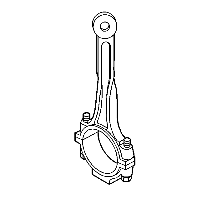
| • | Signs of being twisted, bent, nicked, or cracked |
| • | Scratches or abrasion on the rod bearing seating surface |
| 4.1. | Using an outside micrometer, take two measurements of the piston pin in the area of the connecting rod contact. |
| 4.2. | Using an inside micrometer, measure the bore of the connecting rod piston pin. |
| 4.3. | Subtract the piston pin diameter from the piston pin bore diameter. |
| 4.4. | The clearance should not be more than 0.05 mm (0.0020 in). |
Piston Measurement
- Clean the piston skirts and the pins with a cleaning solvent. DO NOT wire brush any part of the piston.
- Clean the piston-ring grooves with a groove cleaner. Clean the oil ring holes and the slots.
- Inspect the pistons for the following conditions:
- Replace pistons that show any signs of damage or of excessive wear.
- Measure the clearances of the piston pin bore to the piston pin using the following procedure:
- Measure the piston ring end gap using the following procedure:
- Measure the end gap of the piston ring with feeler gages. Compare the measurements with those measurements below:
- Measure the piston ring side clearance with the following procedure:
- Measure piston width using the following procedure:
- If the clearance that is obtained through measurement is greater than these specifications and the cylinder bores are within specification, replace the piston.
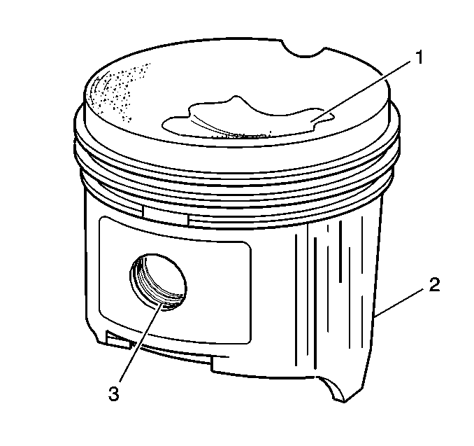
| • | Cracked ring lands, skirts, or pin bosses |
| • | Ring grooves for nicks, burrs that may cause binding |
| • | Warped ring lands or worn ring lands |
| • | Worn areas at the top of the piston (1) |
| • | Scuffed skirts or damaged skirts (2) |
| • | Worn piston pin bores (3) |
| 5.1. | Piston pin bores and pins must be free of varnish or of scuffing. |
| 5.2. | If the clearance is excessive, determine which component is out of specification. |
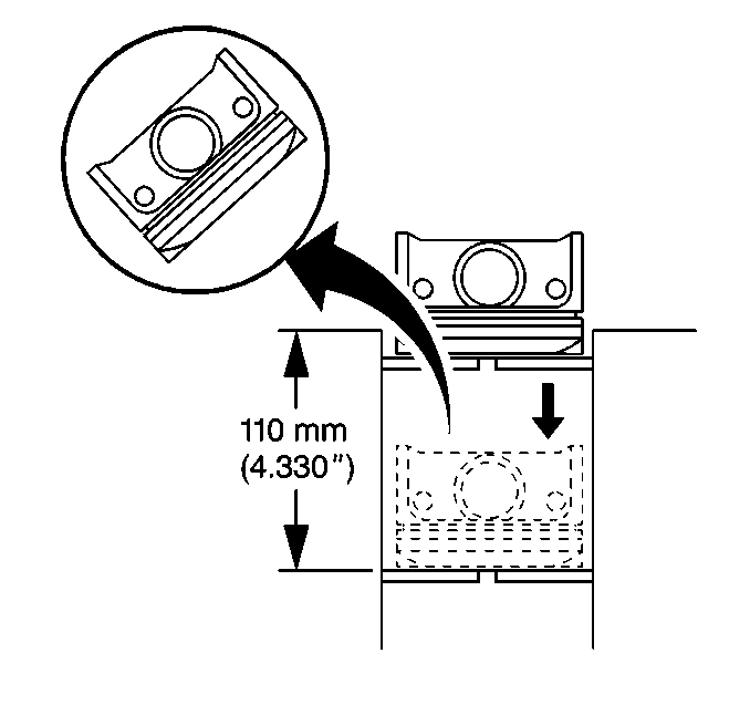
| 6.1. | Place the piston ring in the area of the bore where the piston ring will travel.This is approximately 110 mm or 4 inches down from the deck surface. |
| 6.2. | Square the ring with the cylinder bore by positioning the ring with the piston head. |
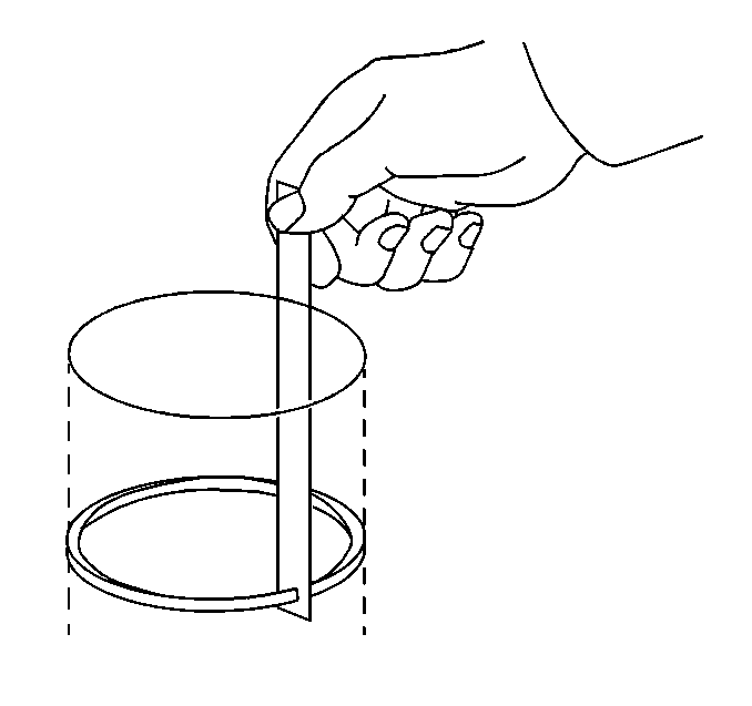
| 7.1. | The end gap of the top compression ring should be 0.15-0.30 mm (0.0098-0.0138 in). |
| 7.2. | The second compression ring end gap should be 0.20-0.35 mm (0.0138-0.0197 in). |
| 7.3. | The oil ring end gap should be 0.20-0.60 mm (0.0059-0.0157 in). |
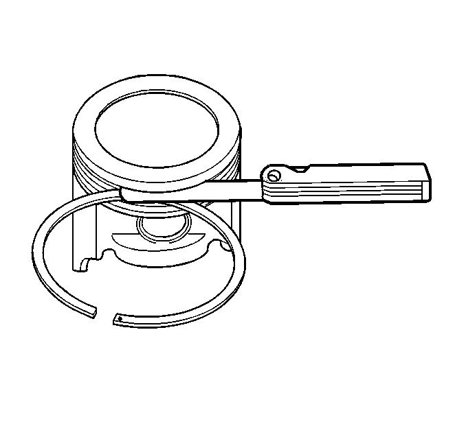
| 8.1. | Roll the top two piston rings entirely around the piston-ring groove. If any binding is caused by the ring groove, dress the groove with a fine file. If any binding is caused by a distorted piston ring, replace the ring. |
| 8.2. | With the piston ring on the piston, use feeler gages in order to check clearance at multiple locations. |
| 8.3. | The clearance between the top piston ring surfaces and the ring land should be no greater than 0.070 mm (0.0027 in). |
| 8.4. | If the clearance is greater than specifications, replace the piston rings. |
| 8.5. | If the new ring does not reduce the top ring side clearance to 0.070 mm (0.0027 in) or less, install a new piston. |
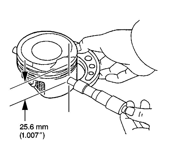
| 9.1. | Using an outside micrometer, measure the width of the piston 25 mm (1 in) below the top of the piston at the thrust surface.Measure this perpendicular to the centerline of the piston pin. |
| 9.2. | Compare the measurement of the piston to the piston's original cylinder by subtracting the piston width from the cylinder diameter. |
| 9.3. | The proper clearance specification for the piston is 0.020-0.040 mm (0.0008-0.0015 in). |
Piston, Connecting Rod, and Bearing Cleaning and Inspection Bearing Selection
Connecting Rod Bearing Selection
- The connecting-rod bearings are of the precision insert type. The connecting-rod bearings are available in standard size and in 0.25 mm (0.0098 in) undersize.
- Inspect the connecting-rod bearing bores or the crankshaft main bearing bores using the following procedure:
- Starting with the number one connecting rod, remove the connecting rod cap nuts.
- Carefully remove the connecting-rod bearing cap.
- Lay a piece of gauging plastic across the number one connecting rod journal of the crankshaft.
- Carefully place the connecting-rod cap onto the connecting rod.
- Install the two connecting-rod bearing cap nuts.
- After reaching the proper torque, remove the two connecting-rod bearing cap nuts of the crankshaft.
- Carefully remove the connecting-rod bearing cap from the connecting rod.
- Measure the gauging plastic (1) at the widest point.
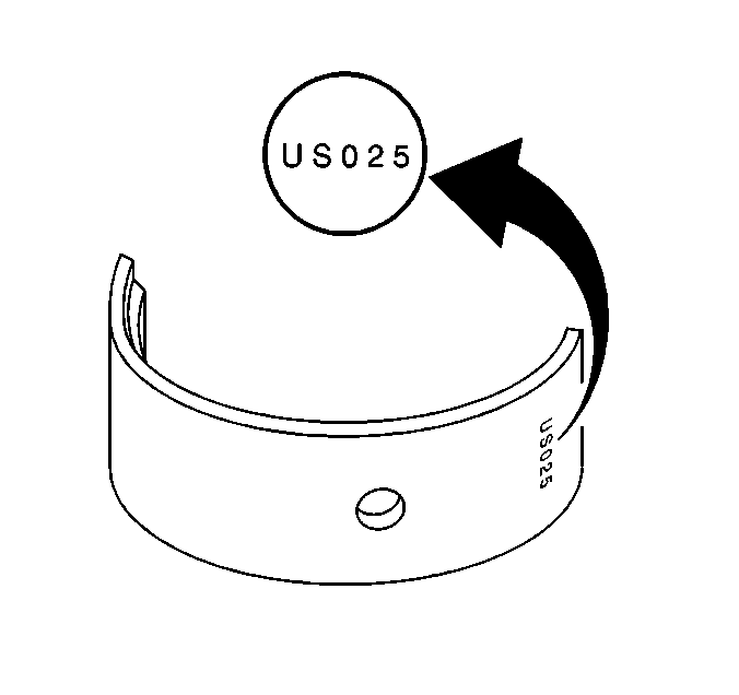
- If bearing replacement is necessary, determine if a standard bearing or an undersized bearing is needed. The undersized bearing is identifiable by a stamping on the back side of the bearing. Refer to Engine Mechanical Specifications in Engine Mechanical for the bearing selection table.
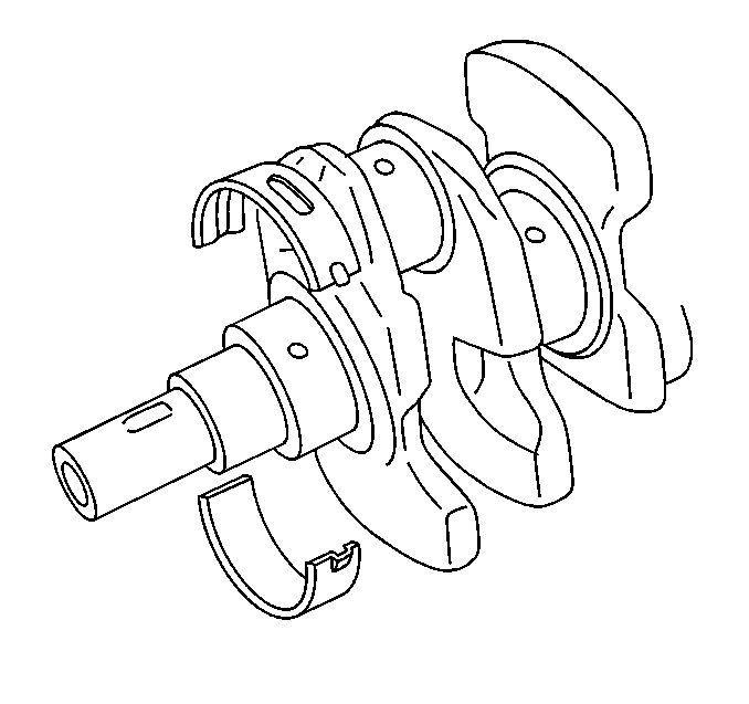
Important: If crankshaft bearing failure is because of abnormal wear, investigate the cause. Inspect the crankshaft or the connecting-rod bearing bores.
| 2.1. | Tighten the bearing cap to specification. |
| 2.2. | Measure the bearing bore for taper and for an out of round condition. |
| 2.3. | A taper or an out of round condition should not exist. |
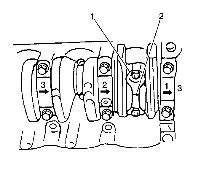
Important: The crankshaft and the main bearing caps must be installed and correctly torqued before measuring the connecting rod clearances.
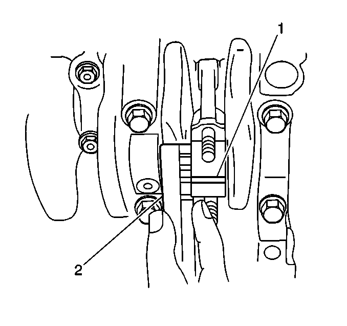
Important: Do not turn the crankshaft while measuring the bearing clearance.
Tighten
Tighten the connecting-rod bearing cap bolts to 35 N·m (26 lb ft).

Standard Oil Clearance:
0.020-0.050 mm (0.0008-0.0019 in)
Maximum Oil Clearance:
0.080 mm (0.0031 in)
