Crankshaft and Bearing Cleaning and Inspection Crankshaft Bearing Inspect
Crankshaft Cleaning and Inspection
Tool Required
J 7872 Magnetic Base Dial Indicator Set
Important: Use care when handling the crankshaft. Avoid damage to the bearing surfaces.
- Clean the crankshaft with solvent.
- Thoroughly clean all oil passages and inspect for restrictions or burrs.
- Dry the crankshaft with compressed air.
- Perform a visual inspection of the crankshaft for damage.
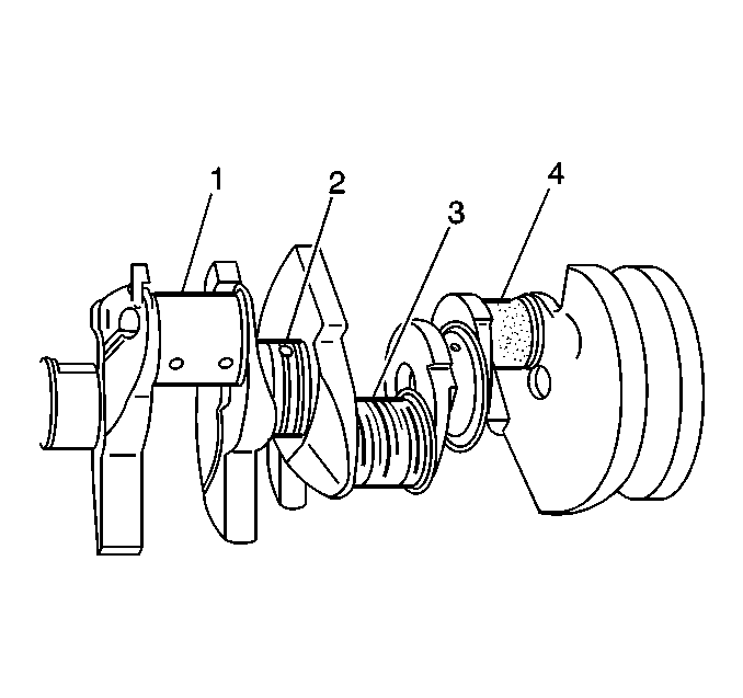
- Inspect the crankshaft journals for wear (1).
- Inspect the crankshaft journals for grooves or scoring (2).
- Inspect the crankshaft journals for scratches or wear (3).
- Inspect the crankshaft journals for pitting or imbedded bearing material (4).
- Measure the crankshaft journals for out-of-round.
- Measure the crankshaft journals for taper.
- Measure the crankshaft runout.
- Use the J 7872 in order to measure the crankshaft runout at the front and rear intermediate journals.
- Use the J 7872 in order to measure the runout of the crankshaft rear flange.
- Replace or repair the crankshaft if the measurements are not within specifications.
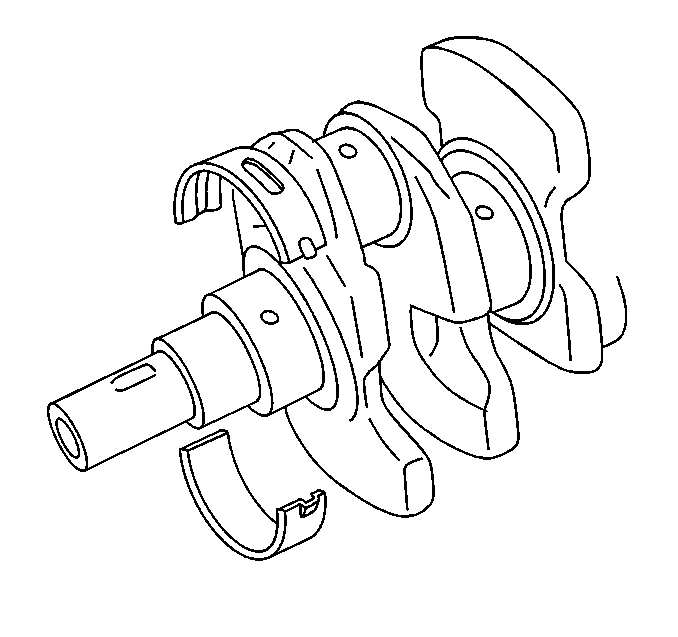
Caution: Wear safety glasses in order to avoid eye damage.
Journals should be smooth with no signs of scoring, wear, or damage.
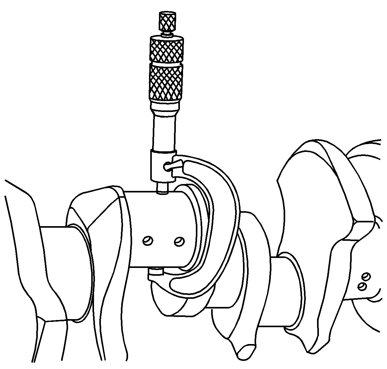
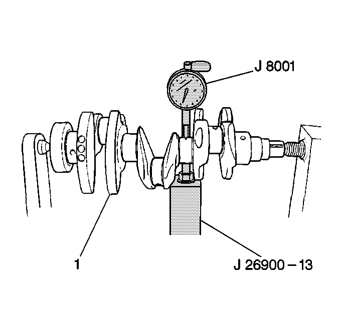
Using a suitable fixture, support the crankshaft (1) on the front and rear journals.
Crankshaft Main Bearing Inspection
- Inspect crankshaft bearings for craters or pockets. Flattened sections on the bearing halves also indicate fatigue.
- Inspect the crankshaft bearings for excessive scoring or discoloration.
- Inspect the crankshaft bearings for dirt or debris imbedded into the bearing material.
- Inspect the crankshaft bearings for improper seating indicated by bright, polished sections of the bearing.
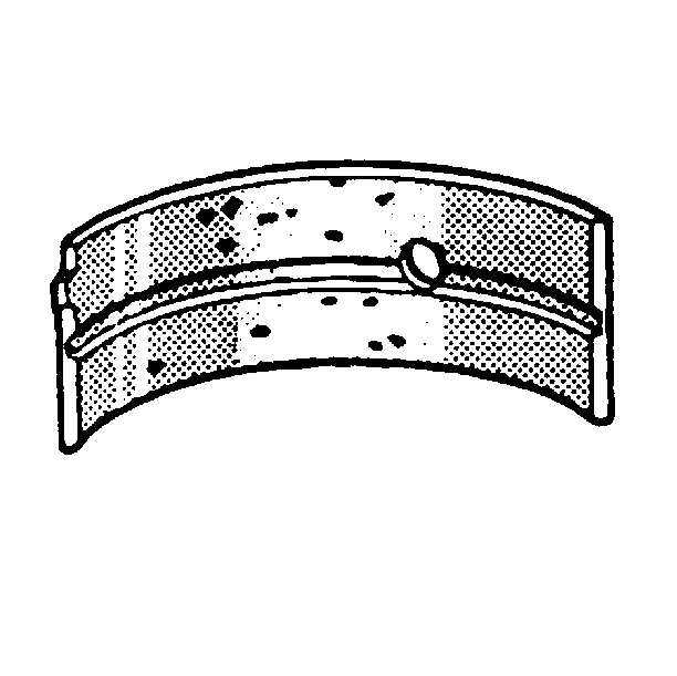
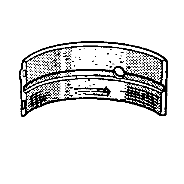
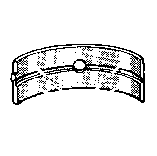
If the lower half of the bearing is worn or damaged, both upper and lower halves should be replaced.
Generally, if the lower half is suitable for use, the upper half should also be suitable for use.
Crankshaft and Bearing Cleaning and Inspection Bearing Selection
Crankshaft Main Bearing Selection
- Inspect the connecting rod bearing bores or crankshaft main bearing bores using the following procedure:
- Install the original crankshaft main bearing inserts on to the cylinder block and the lower crankcase assembly.
- Carefully place the crankshaft on to the bearing inserts in the cylinder block.
- Lay a piece of gaging plastic (1) across each crankshaft main journal.
- Carefully place the lower crankcase assembly on to the cylinder block.
- Install the eight main bearing cap bolts.

Important: If crankshaft bearing failure is due to other than normal wear, investigate the cause. Inspect the crankshaft or connecting rod bearing bores.
| 1.1. | Tighten the bearing cap to specification. |
| 1.2. | Measure the bearing bore for taper and out-of-round. |
| 1.3. | No taper or out-of-round should exist. |

Important: Do not turn the crankshaft while measuring the bearing clearance.
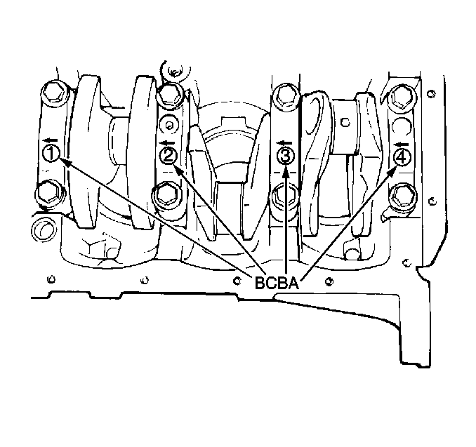
Notice: Use the correct fastener in the correct location. Replacement fasteners must be the correct part number for that application. Fasteners requiring replacement or fasteners requiring the use of thread locking compound or sealant are identified in the service procedure. Do not use paints, lubricants, or corrosion inhibitors on fasteners or fastener joint surfaces unless specified. These coatings affect fastener torque and joint clamping force and may damage the fastener. Use the correct tightening sequence and specifications when installing fasteners in order to avoid damage to parts and systems.
Tighten
Tighten the crankshaft main bearing cap bolts in the sequence shown,
use three progressive steps to obtain 54 N·m (40 lb ft)
Connecting Rod Bearing Selection
- The connecting rod bearings are of the precision insert type. The connecting rod bearings are available in standard and 0.25 mm (0.0098 in) undersize.
- Inspect the connecting rod bearing bores or crankshaft main bearing bores using the following procedure:
- Starting with the number one connecting rod (2), remove the connecting rod cap nuts.
- Carefully remove the connecting rod bearing cap.
- Lay a piece of gaging plastic (1) across the crankshaft number one connecting rod journal.
- Carefully place the connecting rod cap onto the connecting rod.
- Install the two connecting rod bearing cap nuts.
- After reaching the proper torque, remove the two crankshaft connecting rod bearing cap nuts.
- Carefully remove the connecting rod bearing cap from the connecting rod.
- Measure the gaging plastic (1) at its widest point.
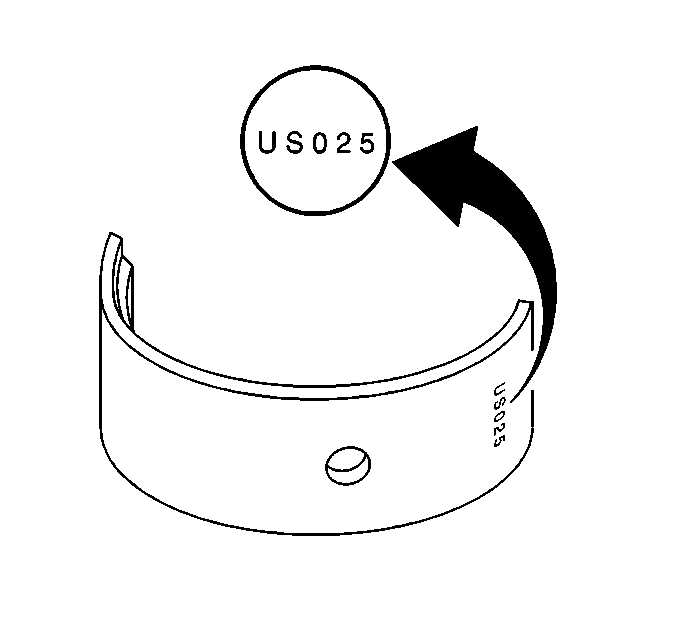
- If bearing replacement is necessary, determine if a standard bearing or an undersized bearing is needed. The undersized bearing is identifiable by a stamping on the backside of the bearing.

Important: If crankshaft bearing failure is due to other than normal wear, investigate the cause. Inspect the crankshaft or connecting rod bearing bores.
| 2.1. | Tighten the bearing cap to specification. |
| 2.2. | Measure the bearing bore for taper and out-of-round. |
| 2.3. | No taper or out-of-round should exist. |
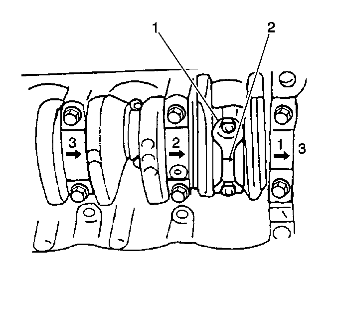
Important: The crankshaft and the main bearing caps must be installed and properly torqued before measuring the connecting rod clearances.
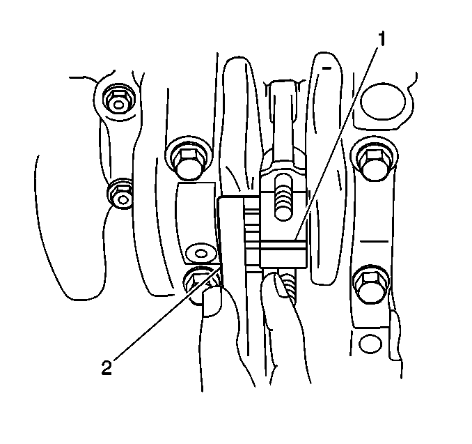
Important: Do not turn the crankshaft while measuring the bearing clearance.
Tighten
Tighten the connecting rod bearing cap bolts to 35N·m (26 lb
ft).

Standard Oil Clearance:
0.020-0.050 mm (0.0008-0.0019 in)
Maximum Oil Clearance:
0.080 mm (0.0031 in)
