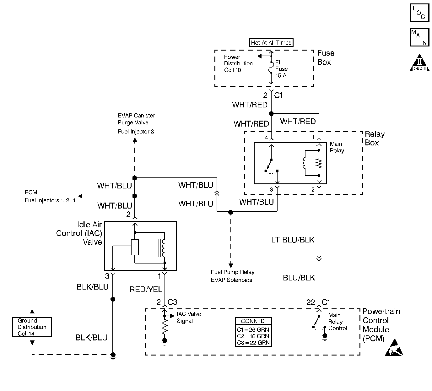
Circuit Description
The powertrain control module (PCM) controls the idle air control (IAC) valve in order to regulate the airflow through the idle air bypass passage. The amount of airflow through the idle air bypass passage determines the idle speed. Engine load regulates the IAC valve. A malfunctioning IAC valve may cause a stalling condition.
Conditon for Running the DTC
| • | The engine coolant temperature between 70°C to 110°C (158°F - 230°F). |
| • | The throttle position (TP) sensor indicates a closed throttle position. |
| • | The engine is running. |
Conditions for Setting the DTC
The engine idle speed is 100 RPM or less than the desired idle.
Action Taken When the DTC Sets
| • | The PCM illuminates the malfunction indicator lamp (MIL) after two consecutive ignition cycles in which the diagnostic runs with the fault active. |
| • | The PCM records operating conditions at the time that the diagnostic fails. The Freeze Frame buffer stores this information. |
Conditions for Clearing the MIL/DTC
| • | The MIL turns off after three consecutive drive cycles without a fault present. |
| • | A DTC will clear after 40 consecutive warm-up cycles without a fault. |
| • | Use the Clear DTC Information function on the scan tool, or disconnect the PCM battery feed in order to clear the DTC. |
Diagnostic Aids
Check for any of the following conditions:
| • | An incorrect engine idle speed--Refer to Idle Speed Inspection . |
| • | A restricted air intake system--Check for a collapsed air intake duct, for a restricted air filter element, or for foreign objects that are blocking the air intake system. |
| • | Inspect the throttle body for any of the following conditions: |
| - | Check the throttle plate for smooth movement and for even movement. |
| - | Check for excessive deposits in the IAC passage. |
| - | Check for excessive deposits in the throttle bore or on the throttle plate. |
| - | Check for objects that are blocking the IAC passage or the throttle bore. |
| • | Check for a large vacuum leak. Check for a crankcase ventilation valve that is incorrectly installed or is faulty, or for a disconnected brake booster hose.These conditions can cause a large vacuum leak. |
A fault in the IAC valve electrical connection may cause an intermittent condition. Inspect the wiring harness and the components for any of the following conditions:
| • | Backed out terminals |
| • | Incorrect mating of terminals |
| • | Broken electrical connector locks |
| • | Incorrectly formed terminals or damaged terminals |
| • | Faulty terminal-to-wire connections |
| • | Physical damage to the wiring harness |
| • | A broken wire inside the insulation |
| • | Corrosion of electrical connections, of splices, or of terminals |
If a DTC P0506 cannot be duplicated, the Freeze Frame data can be useful in determining vehicle operating conditions when the DTC was set.
Test Description
The numbers below refer to the step numbers in the diagnostic table.
-
The Powertrain OBD System Check prompts the technician to complete some basic checks, and to save the applicable Freeze Frame data on the scan tool. This creates an electronic copy of the data that was taken when the fault occurred. The scan tool saves the information for later reference.
-
An inspection may find a problem and may reduce the diagnostic time.
-
This step checks the battery positive voltage circuit from the IAC valve for an open or for a short.
-
This step checks the battery positive voltage circuit from the IAC valve for the correct voltage reading.
-
This step checks the IAC valve ground circuit.
-
This step checks the IAC valve control circuit for a short to voltage.
-
This step determines whether the fault is caused by the PCM or by the IAC valve.
Step | Action | Value(s) | Yes | No | ||||||||||
|---|---|---|---|---|---|---|---|---|---|---|---|---|---|---|
Did you perform the Powertrain On-Board Diagnostic (OBD) System Check? | -- | |||||||||||||
2 |
Does the scan tool display indicate the IAC duty cycle is within the specified range? | 8-25 % or about 35% at 2 000 m (6562 ft) above the see level. | Go to Diagnostic Aids | |||||||||||
Was a repair necessary? | -- | |||||||||||||
Did the test lamp illuminate? | -- | |||||||||||||
Probe terminal 2 on the harness side of the IAC valve electrical connector with a DMM. Did the DMM read the specified value? | B+ | |||||||||||||
Repair the open or the short in the battery positive voltage circuit between the IAC valve and the main relay. Refer to Wiring Repairs in Wiring Systems. Is the action complete? | -- | -- | ||||||||||||
7 | Probe terminal 3 on the harness side of the IAC valve electrical connector with a test lamp to battery positive voltage. Did the test lamp illuminate? | -- | ||||||||||||
8 | Repair the open in the IAC valve ground circuit. Refer to Wiring Repairs in Wiring Systems. Is the action complete? | -- | -- | |||||||||||
Does the DMM indicate voltage? | -- | |||||||||||||
Does the engine speed fluctuate when the test lamp is contacting the terminal? | -- | |||||||||||||
11 |
Was a repair necessary? | -- | ||||||||||||
12 | Replace the IAC Valve. Refer to Idle Air Control Valve Replacement . Is the action complete? | -- | -- | |||||||||||
13 | Replace the PCM. Is the action complete? | -- | -- | |||||||||||
14 |
Does the scan tool display any DTCs? | -- | Go to the applicable DTC table | System OK |
