| Table 1: | Crankshaft Position (CKP) Sensor |
| Table 2: | Diode Module |
| Table 3: | Engine Coolant Temperature (ECT) Sensor |
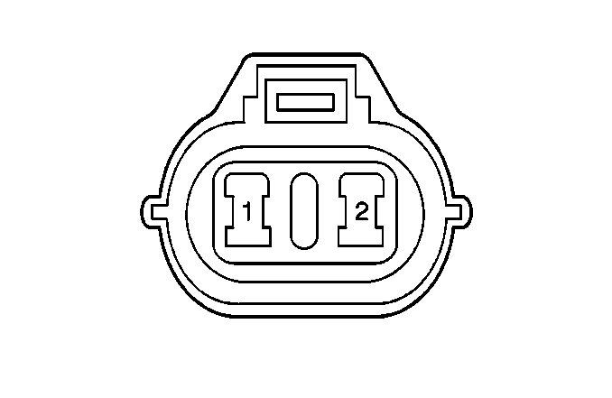
| Table 4: | EVAP Canister Purge Valve |
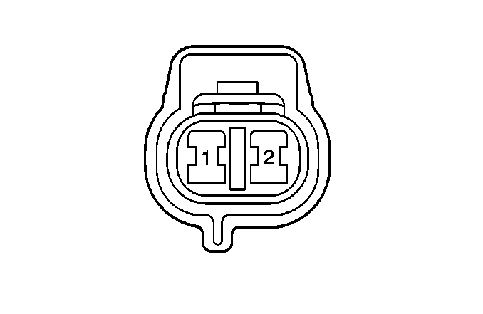
| Table 5: | EVAP Canister Vent Solenoid |
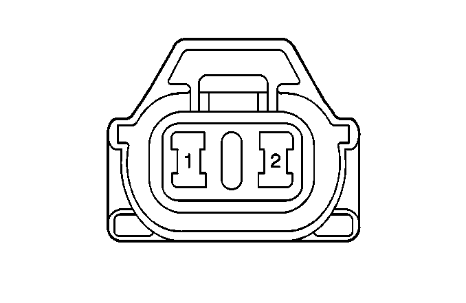
| Table 6: | EVAP Tank Pressure Control Solenoid Vacuum Valve |
| Table 7: | Fuel Injector #1 |
| Table 8: | Fuel Injector #2 |
| Table 9: | Fuel Injector #3 |
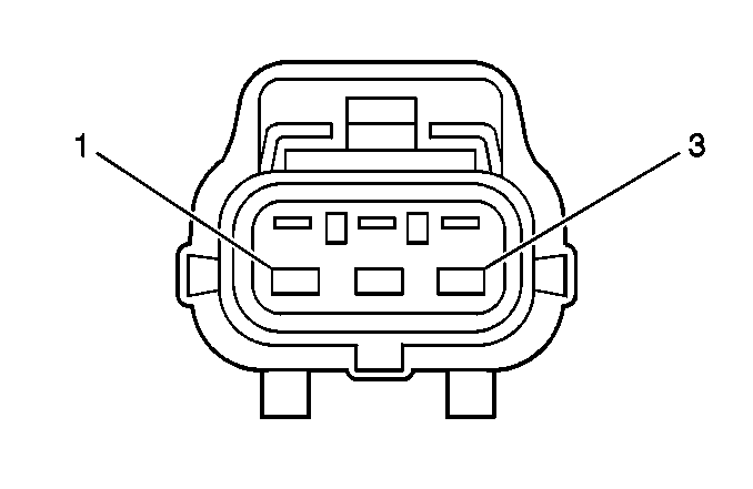
| Table 10: | Fuel Injector #4 |
| Table 11: | Fuel Tank Pressure Sensor |
| Table 12: | HO2S1 |
| Table 13: | Idle Air Control (IAC) Valve |
| Table 14: | Intake Air Temp (IAT) Sensor |
| Table 15: | Manifold Absolute Pressure (MAP) Sensor |
| Table 16: | TP Sensor |
| Table 17: | Vehicle Speed Sensor (VSS) |
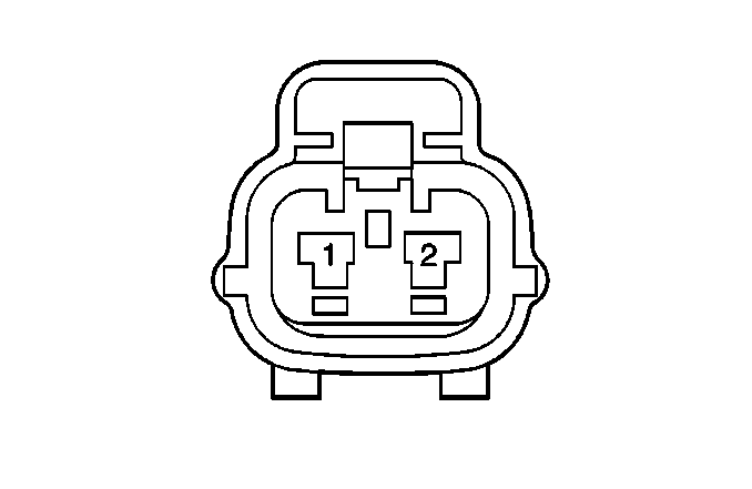
| ||||||
|---|---|---|---|---|---|---|
Connector Part Information |
| |||||
Pin | Wire Color | Function | ||||
1 | WHT/BLK | Ignition Reference - High | ||||
2 | WHT/RED | Ignition Reference - Low | ||||
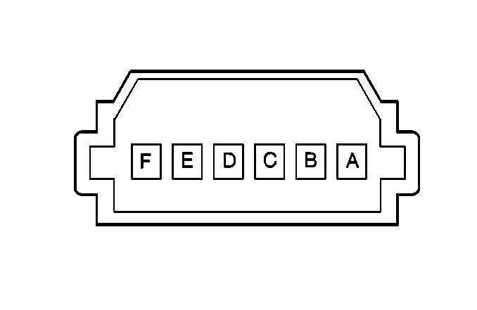
| ||||||
|---|---|---|---|---|---|---|
Connector Part Information |
| |||||
Pin | Wire Color | Function | ||||
A | BRN/YEL | (PCM) Electrical Load Idle-Up Signal | ||||
B | PNK/BLK | Not Used | ||||
C | RED/WHT | Rear Defogger Indicator | ||||
D | RED/YEL | Light 1 Relay Output | ||||
E | BLK/RED | Dome Lamp Control | ||||
F | BLK/BLU | Door Open Signal | ||||
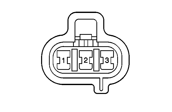
| ||||||
|---|---|---|---|---|---|---|
Connector Part Information |
| |||||
Pin | Wire Color | Function | ||||
1 | GRA/WHT | ECT Input | ||||
2 | YEL/WHT | Not Used | ||||
3 | GRN/BLK | Sensor Ground | ||||
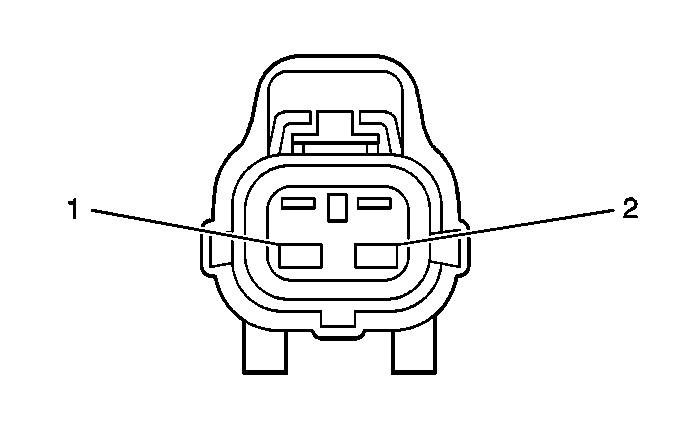
| ||||||
|---|---|---|---|---|---|---|
Connector Part Information |
| |||||
Pin | Wire Color | Function | ||||
1 | RED/GRN | EVAP CPV Control | ||||
2 | WHT/BLU | Main Relay | ||||
| ||||||
|---|---|---|---|---|---|---|
Connector Part Information |
| |||||
Pin | Wire Color | Function | ||||
1 | RED/GRN | EVAP CVS Control | ||||
2 | WHT/BLU | Main Relay | ||||
| ||||||
|---|---|---|---|---|---|---|
Connector Part Information |
| |||||
Pin | Wire Color | Function | ||||
1 | WHT/BLU | Main Relay | ||||
2 | YEL | EVAP Tank Pressure Control Solenoid Vacuum Valve Control | ||||
| ||||||
|---|---|---|---|---|---|---|
Connector Part Information |
| |||||
Pin | Wire Color | Function | ||||
1 | BRN/WHT | Fuel Injector No. 1 Control | ||||
2 | WHT/BLU | Main Relay | ||||

| ||||||
|---|---|---|---|---|---|---|
Connector Part Information |
| |||||
Pin | Wire Color | Function | ||||
1 | BRN/RED | Fuel Injector No. 2 Control | ||||
2 | WHT/BLU | Main Relay | ||||

| ||||||
|---|---|---|---|---|---|---|
Connector Part Information |
| |||||
Pin | Wire Color | Function | ||||
1 | BRN/BLK | Fuel Injector No. 3 Control | ||||
2 | WHT/BLU | Main Relay | ||||

| ||||||
|---|---|---|---|---|---|---|
Connector Part Information |
| |||||
Pin | Wire Color | Function | ||||
1 | BRN/YEL | Fuel Injector No. 4 Control | ||||
2 | WHT/BLU | Main Relay | ||||
| ||||||
|---|---|---|---|---|---|---|
Connector Part Information |
| |||||
Pin | Wire Color | Function | ||||
1 | LT GRN/YEL | Ignition Fuel Tank Pressure Input | ||||
2 | LT GRN/BLK | Sensor Ground | ||||
3 | LT GRN | Reference voltage | ||||
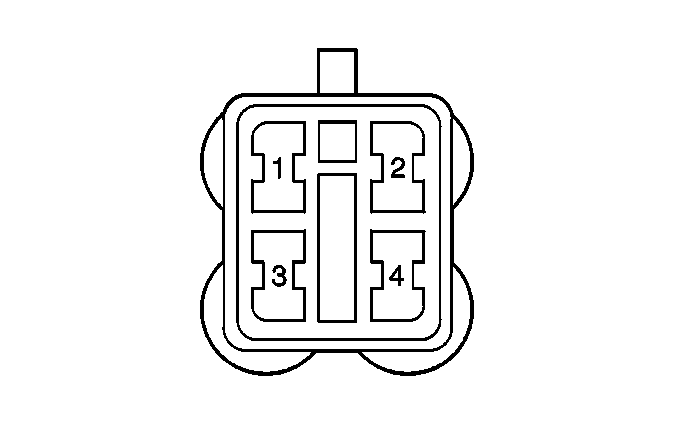
| ||||||||
|---|---|---|---|---|---|---|---|---|
Connector Part Information |
| |||||||
Pin | Wire Color | Function | ||||||
1 | GRN/BLK | Sensor Ground | ||||||
2 | RED | HO2S1 Signal | ||||||
3 | PNK/BLK | HO2S1 Heater Control | ||||||
4 | BLK/WHT | IG Coil Fuse | ||||||
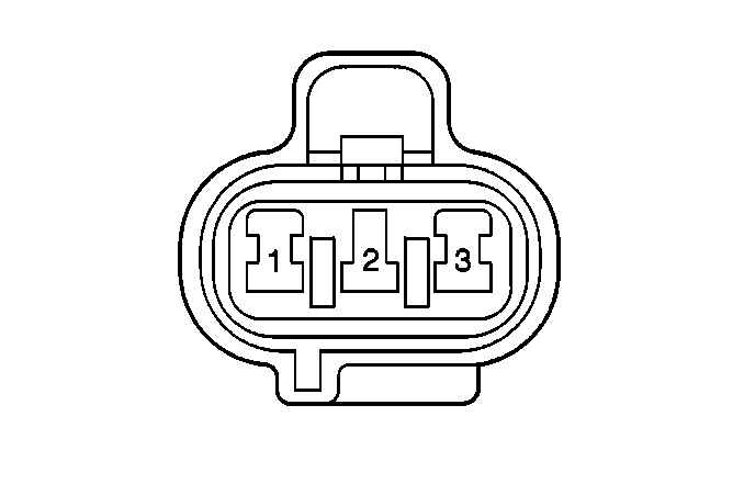
| ||||||||
|---|---|---|---|---|---|---|---|---|
Connector Part Information |
| |||||||
Pin | Wire Color | Function | ||||||
1 | RED/YEL | IAC Valve Signal | ||||||
2 | WHT/BLU | Fuel Injectors | ||||||
3 | BLK/BLU | Ground - G104 | ||||||
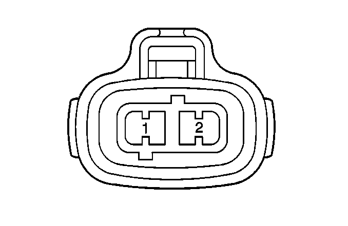
| ||||||||
|---|---|---|---|---|---|---|---|---|
Connector Part Information |
| |||||||
Pin | Wire Color | Function | ||||||
1 | GRN/BLK | Sensor Ground | ||||||
2 | GRA | IAT Input | ||||||
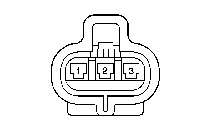
| ||||||||
|---|---|---|---|---|---|---|---|---|
Connector Part Information |
| |||||||
Pin | Wire Color | Function | ||||||
1 | ORN/GRN | Sensor Ground | ||||||
2 | LT GRN | MAP Input | ||||||
3 | LT GRN | Reference Voltage | ||||||
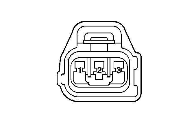
| ||||||||
|---|---|---|---|---|---|---|---|---|
Connector Part Information |
| |||||||
Pin | Wire Color | Function | ||||||
1 | GRN/BLK | Sensor Ground | ||||||
2 | LT GRN | Reference Voltage | ||||||
3 | GRN/WHT | Throttle Position Input | ||||||

| ||||||
|---|---|---|---|---|---|---|
Connector Part Information |
| |||||
Pin | Wire Color | Function | ||||
1 | PPL | VSS High (AT) | ||||
2 | GRY/YEL | VSS Low (AT) | ||||
