Tools Required
| • | J 34844 Transaxle
Shaft Bearing Installer |
| • | J 36850 Transjel®
Transmission Assembly Lubricant |
| • | J 35283 Input
Gear Bearing Installer |
Removal Procedure
Notice: Observe the hydraulic pressure gage during input shaft disassembly.
Pressure on the input shaft or its components should not exceed 4990 kg
(11,000 lb). If pressure higher than specified is needed
for input shaft disassembly, the input shaft may be misaligned in the press
support. Reset the press and press support before resuming input shaft disassembly
or damage to the input shaft and its components may occur.
Important: In order to avoid placing undue stress on the gear teeth during removal,
invert the J 22912-O1
so
that the flat side of the J 22912-O1
is facing upward during disassembly of the input shaft assembly.
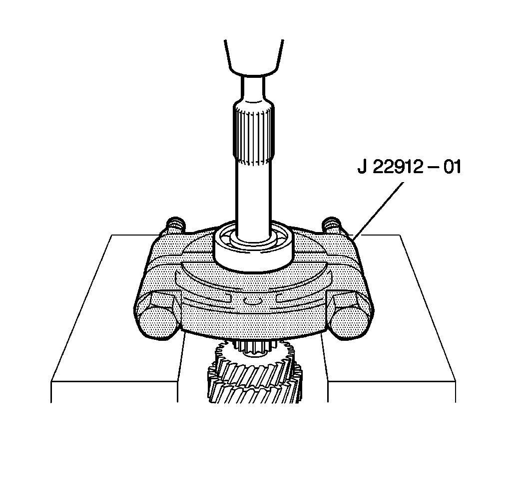
- Use the J 22912-O1
and an arbor press in order to remove
the right input shaft bearing from the input shaft.
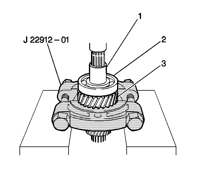
- Use the J 22912-O1
and an arbor press in order to simultaneously
remove the following components from the input shaft:
| • | The fifth gear spacer (1) |
| • | The left input shaft bearing (2) |
| • | The input shaft fourth gear (3) |
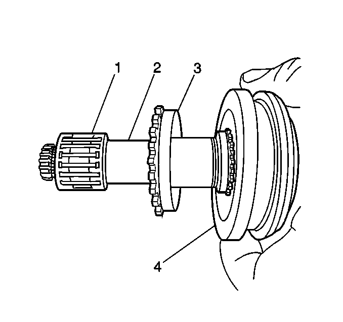
- Remove the following components
from the input shaft:
| 3.1. | The third and fourth gear bearing (1) |
| 3.2. | The high speed synchronizer ring (2) |
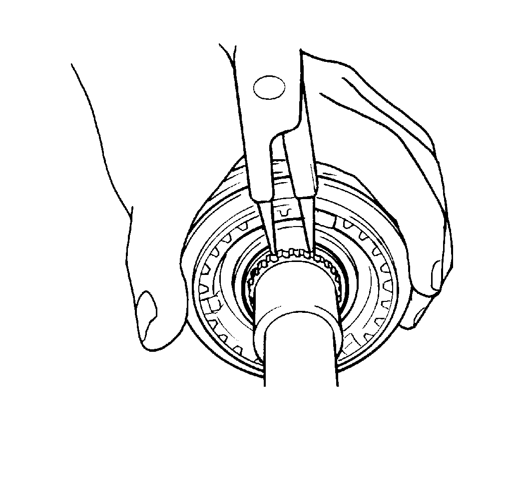
- Remove the high speed
synchronizer snap ring from the input shaft.
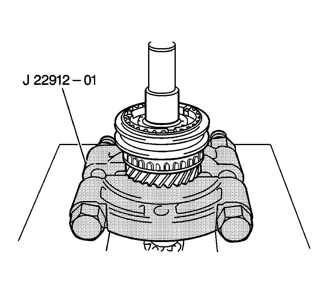
- Use the J 22912-O1
and an arbor press in order to remove
the following components simultaneously from the input shaft:
| • | The high speed sleeve and hub |
| • | The high speed synchronizer ring |
| • | The input shaft third gear |
- Remove the third and fourth gear bearing from the input shaft.
- Remove the high speed sleeve from the high speed hub.
- Remove the high speed synchronizer spring from the high speed
hub.
- Clean all components with clean solvent. Dry the components thoroughly.
- Inspect the input shaft for the following conditions and replace
as necessary:
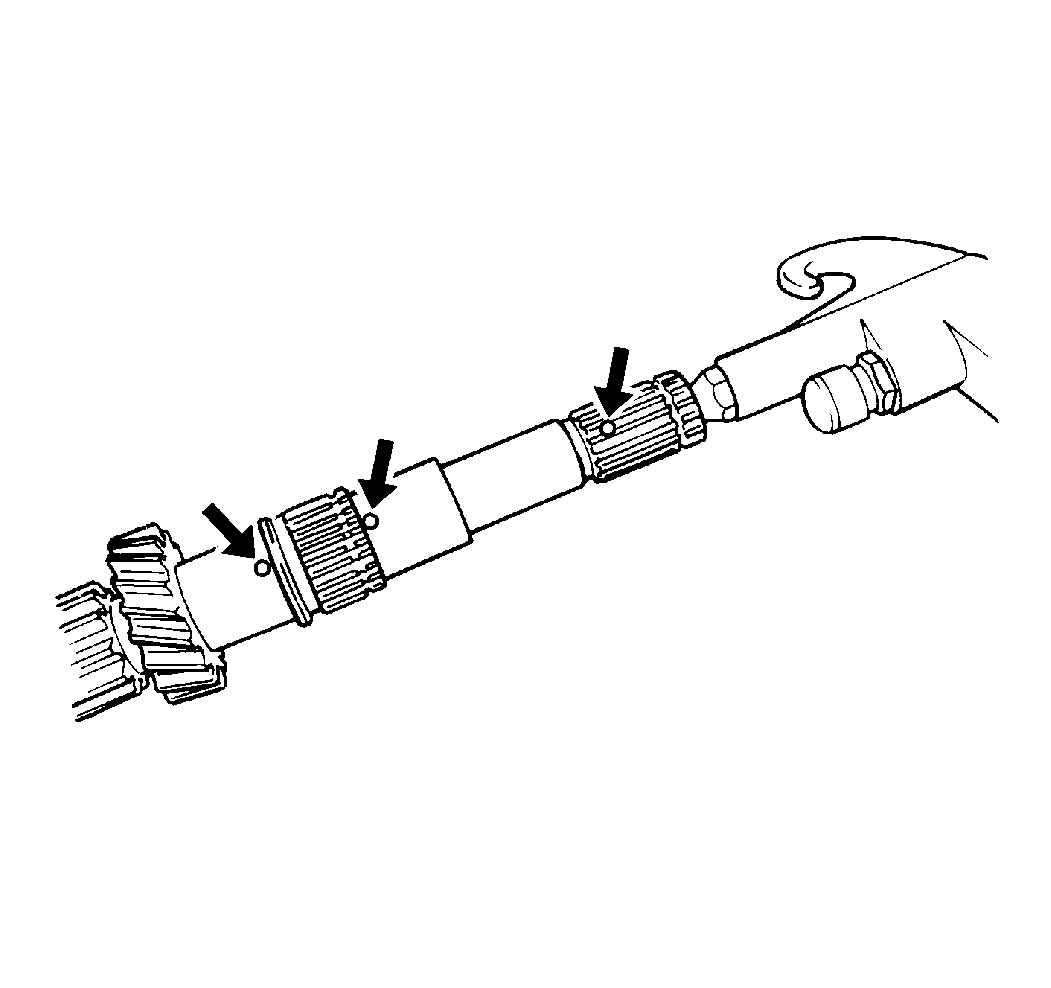
- Inspect the shaft oil
passages for obstructions:
| • | Apply compressed air into the end of the input shaft. |
| • | If air does not flow freely out of the input shaft oil passages,
replace the input shaft. |
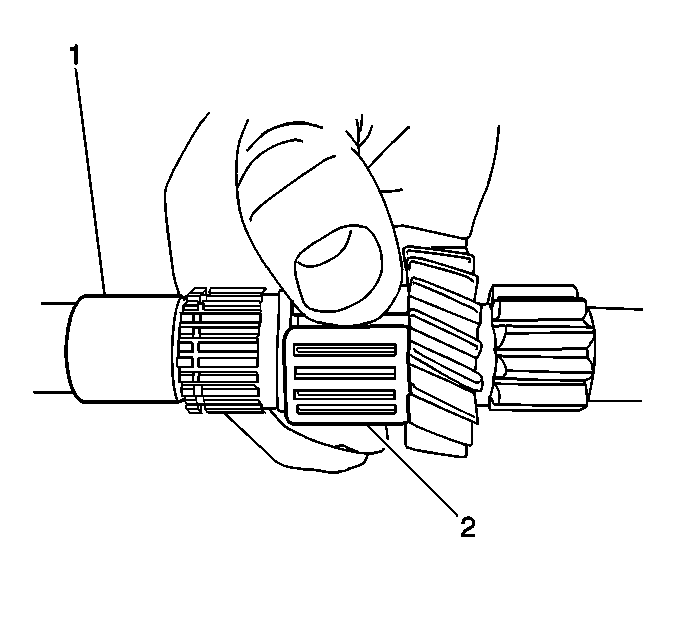
- Inspect all the bearings
(2) for the following conditions and replace as necessary:
- Inspect all of the gears for the following conditions and replace
as necessary:
- Inspect all of the synchronizer components for the following conditions
and replace as necessary:
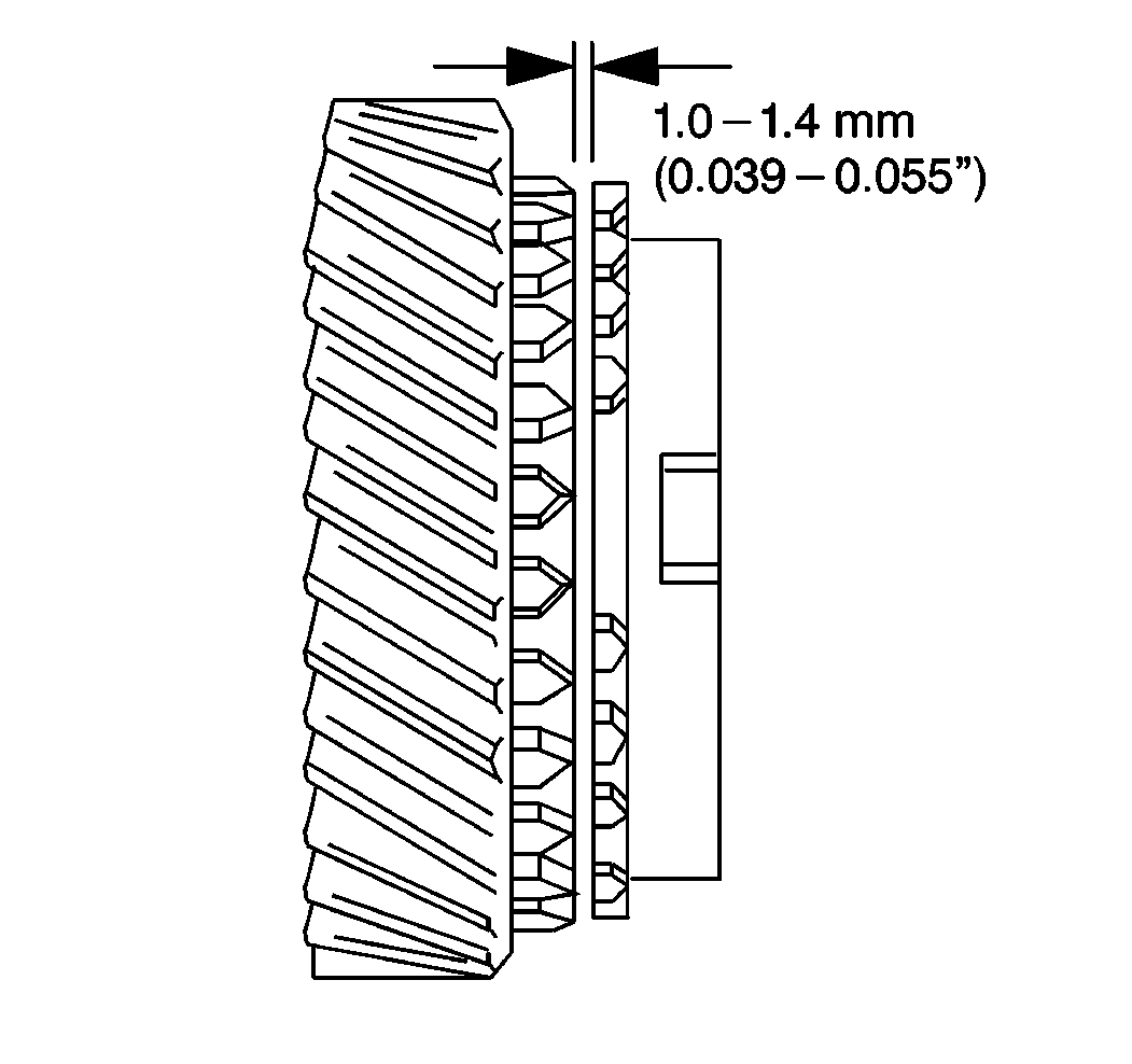
- Use a feeler gage in order
to measure the clearance between the input shaft fourth gear and the high
speed synchronizer ring and gear.
Standard clearance is 1.0-1.4 mm (0.039-0.055 in).
If the clearance is below 0.5 mm (0.019 in), replace the
high speed synchronizer ring and the input shaft fourth gear.
- Use a feeler gage in order to measure the clearance between the
input shaft third gear and the high speed synchronizer ring and gear.
The standard clearance is 1.0-1.4 mm (0.039-0.055 in).
If the clearance is below 0.5 mm (0.019 in), replace the
high speed synchronizer ring and the input shaft third gear.
- Use a feeler gage in order to measure the clearance between the
input shaft fifth gear and the fifth speed synchronizer ring and gear.
The standard clearance is 1.0-1.4 mm (0.039-0.055 in).
If the clearance is below 0.5 mm (0.019 in), replace the
fifth speed synchronizer ring and the input shaft fifth gear.
Installation Procedure
- Apply a thin coat of J 36850
to all of the parts before assembly.
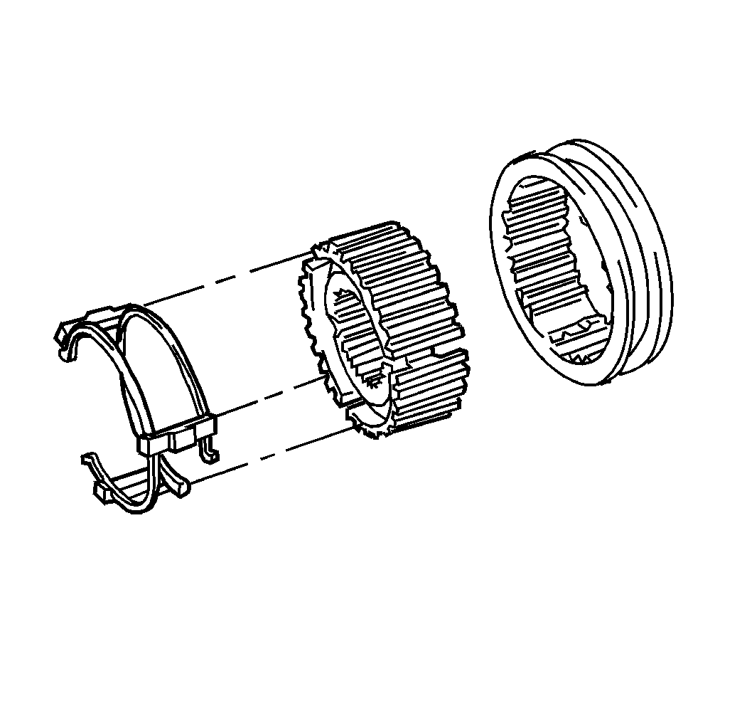
- Install the high speed
synchronizer springs to the high speed hub.
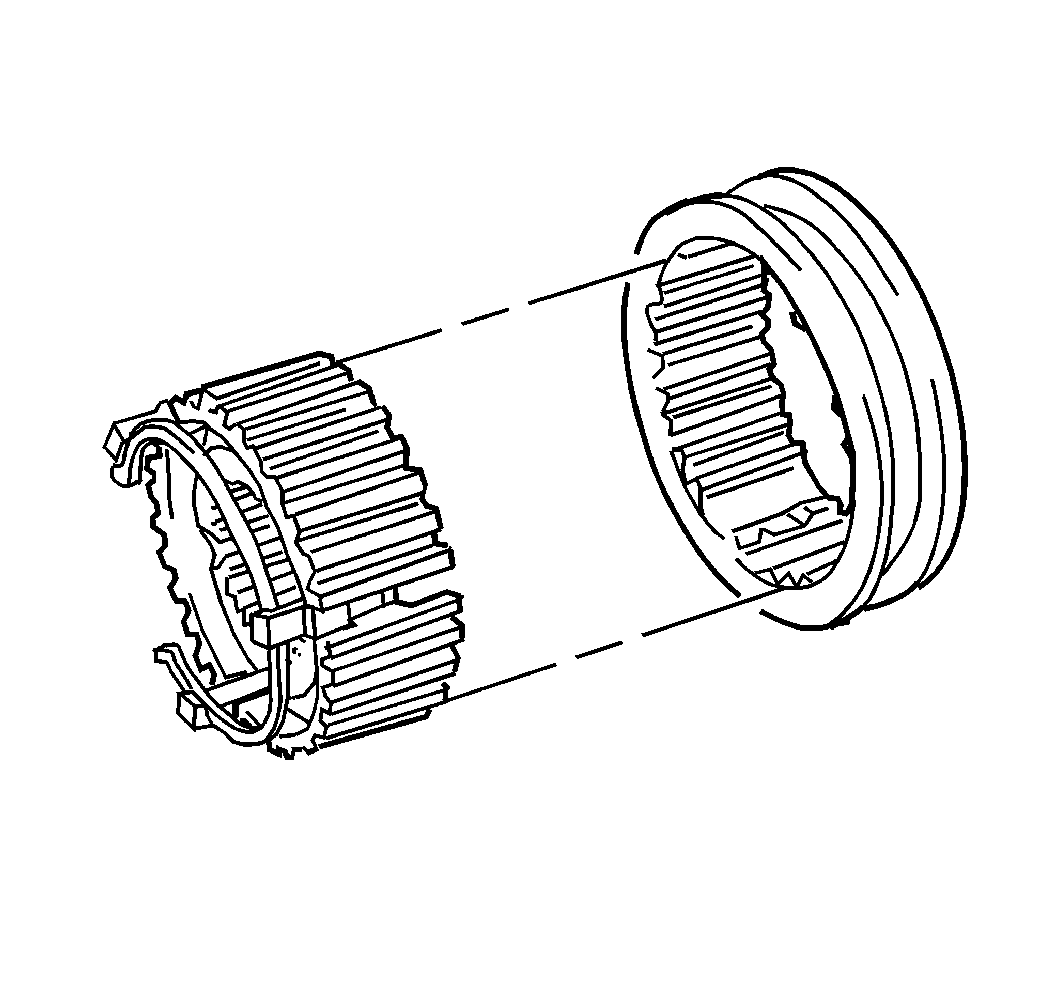
- Install the high speed
sleeve onto the high speed hub.
- Install the third and fourth gear bearing onto the input shaft.
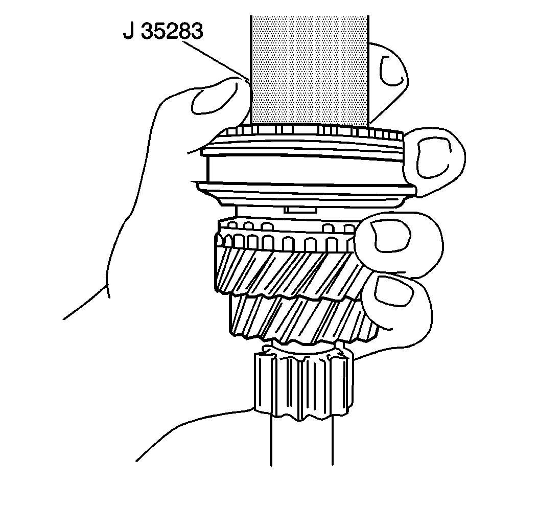
Important: When pressing the high speed sleeve and hub onto the input shaft, make
sure that the synchronizer keys are aligned with the keyways in the high speed
hub.
- Use the J 35283
and
an arbor press in order to install the following components onto the input
shaft:
| • | The input shaft third gear |
| • | The high speed synchronizer ring |
| • | The high speed sleeve and hub |
- Inspect the input shaft third gear for smooth rotation.
If the input shaft third gear does not rotate smoothly, remove and reinstall
the input shaft third gear until smooth rotation is obtained.
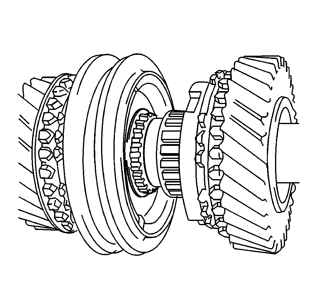
- Install the high speed
synchronizer snap ring onto the input shaft.
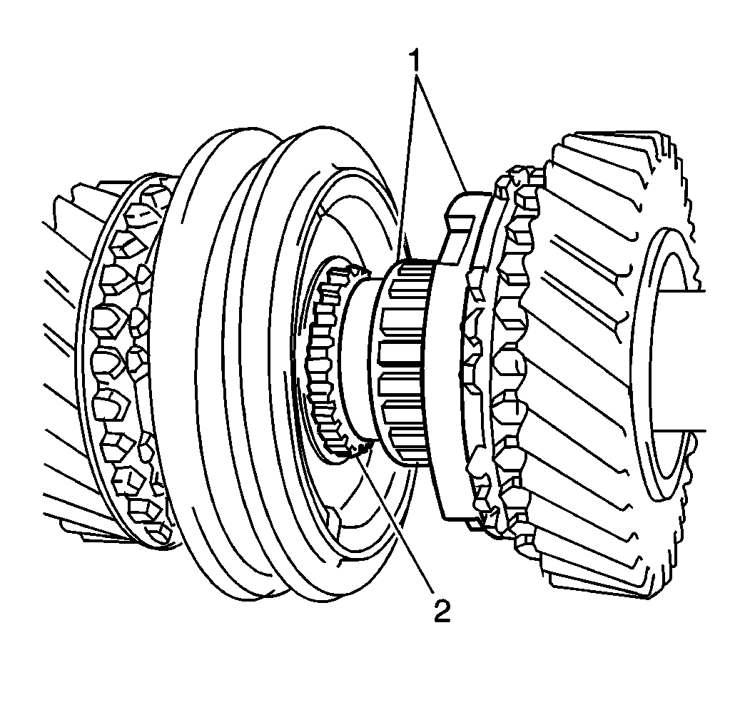
Important: To prevent distortion of the fifth gear spacer upon installation, install
the input shaft fourth gear and the left input shaft bearing first, then install
the fifth gear spacer separately.
- Install the third and fourth gear bearing and the high speed synchronizer
ring onto the input shaft (2).
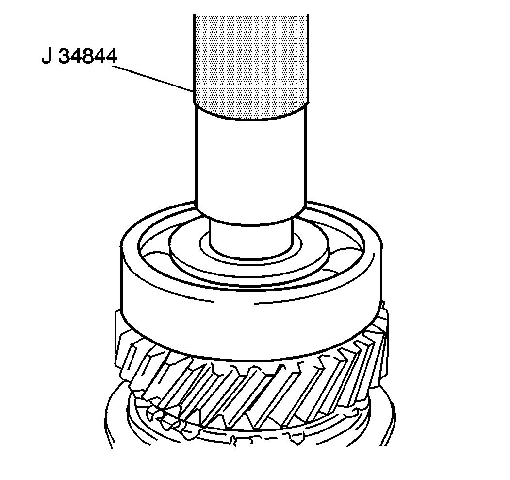
- Use the J 34844
and an arbor press in order to install
the input shaft fourth gear and the left input shaft bearing simultaneously.
- Use the J 34844
and
a arbor press in order to install the fifth gear spacer onto the input shaft.
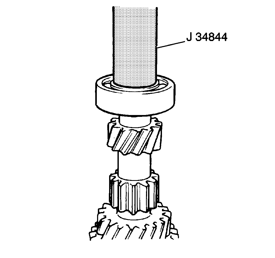
- Use the J 34844
in order to install the right input
shaft bearing onto the input shaft.


