Product Enhancement for Inventory and Customer Vehicles-Retractable Hardtop Latch-Expires with Base Warranty

| Subject: | 06050 -- Product Enhancement for Inventory and Customer Vehicles - Retractable Hardtop Latch - Expires with Base Warranty |
| Models: | 2006 Pontiac G6 |
| With Retractable Hardtop |
This product enhancement includes vehicles in dealer/retailer inventory and customer vehicles that return for any type of service, and will expire at the end of the involved vehicle's New Vehicle Limited Warranty period.
Purpose
This bulletin provides a service procedure to inspect, and if necessary, replace the latch assembly. On rare occasions, the roof latch rod weld may fracture. If it fractures, the latch will not engage. The roof would be held down by the opposite latch but the occupant would hear a rattling sound and/or wind noise.
This service procedure should be completed as soon as possible on involved vehicles currently in dealer inventory and customer vehicles that return to the dealer for any type of service during the New Vehicle Limited Warranty coverage period, at which time this bulletin will expire.
Vehicles Involved
A list of involved vehicles currently in dealer inventory is attached to the Administrative Message (US) or Dealer Communication (Canada) used to release this bulletin. Customer vehicles that return for service, for any reason, and are still covered under the vehicle's base warranty, and are within the VIN breakpoints provided below, should be checked for vehicle eligibility in the appropriate system.
Year | Division | Model | From | Through |
|---|---|---|---|---|
2006 | Pontiac | G6 | 64283104 | 64291426 |
Important: Dealers/retailers are to confirm vehicle eligibility prior to beginning repairs by using GMVIS. Not all vehicles within the above breakpoints may be involved.
Parts Information
Parts required to complete this recall are to be obtained from General Motors Service and Parts Operations (GMSPO). Please refer to your "involved vehicles listing" before ordering parts. Normal orders should be placed on a DRO=Daily Replenishment Order. In an emergency situation, parts should be ordered on a CSO=Customer Special Order.
Part Number | Description | Qty/ Vehicle |
|---|---|---|
10364421* | Actuator, F/Top Frt Lat | 1 |
*Very few vehicles will require an actuator. | ||
Service Procedure
Vehicle Inspection
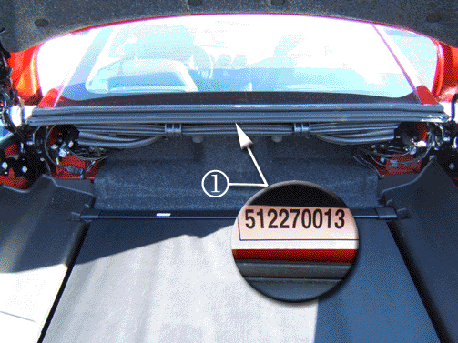
Open the trunk and locate the roof label (1).
| • | If the number is within the range of 605220026 through 606010070, replace the latch assembly. Proceed to the section below titled, Latch Replacement. |
| • | If the number is not within the range of 605220026 through 606010070, no action is required. |
Latch Replacement
Tools Required
-- BO 48120 Folding Top Retaining Strap
- Move the roof top to the service position and install the top restraining straps using B0 48120, Folding Top Retaining Strap. Refer to Folding Top Retaining Strap Installation procedure in SI.
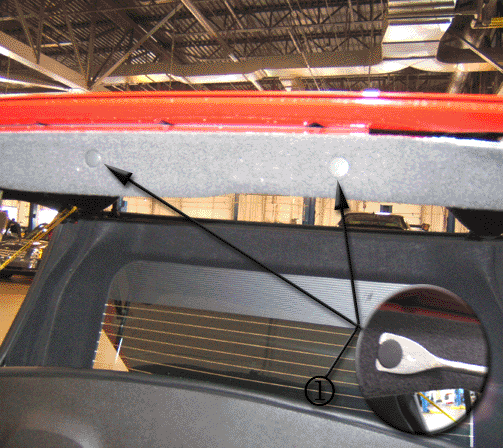
- Remove the front and rear push-pins (1) from the front panel of the headliner.
- Carefully remove the headliner from the vehicle. Do not damage the small "wings" on the side of the headliner when removing the headliner.
- Remove the top restraining straps and fully close the roof to the header using the switch on the header.
- Mark the position of the bell crank bracket to the front roof panel.
- Disconnect the right and left rod ends from the header latches by pulling them off of the ball stud.
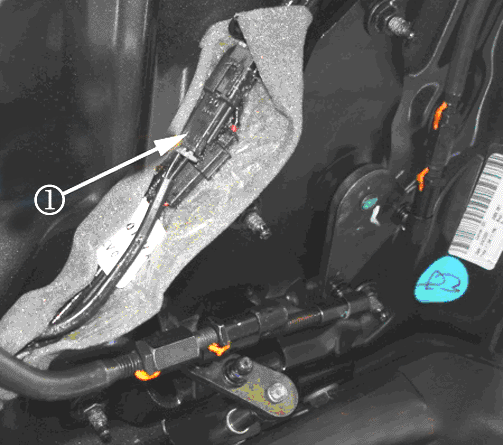
- Unwrap the foam tape from the line bundle and disconnect S14 pigtail connector (1). Do not damage the small locking tab on the connector.
- Unwrap the wire pigtail from the hoses.
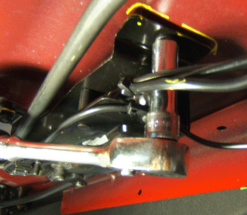
- Remove the three M6 10 mm (25/64 in) bolts from the bell crank bracket.
- Remove the hydraulic cylinder attaching the J-clips and pins from the assembly. There are two J-clips, which are located on opposite ends of the latch assembly.
- Remove the hydraulic cylinder from the bell crank assembly by pulling it out toward the passenger side of the vehicle.
- Install the hydraulic cylinder into the bell crank assembly.
- Install the J-clips and pins to the latch assembly.
- Align the bell crank bracket to the front of the roof panel. Use the position marks created in Step 5.
- Install the three M6 10 mm (25/64 in) bolts to the bell crank bracket.
- Connect the S14 pigtail connector (1).
- Wrap the line bundle to the hoses with the foam tape.
- Connect the right and left rod ends from the header latches to the ball studs.
- Open the roof using the switch on the header. Proceed to the section below titled, "Roof Functional Test.
- Move the roof top to the service position and install the top restraining straps, BO 48120. Refer to Folding Top Retaining Strap Installation procedure in SI.
- Install the headliner to the roof.

Important: tart the vehicle. Do not turn the vehicle OFF until the restraining straps are in place.


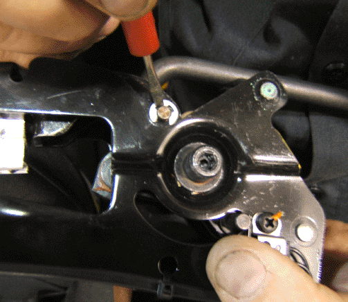


Tighten
Tighten the M6 bolts to 10 N·m(89 lb in).


Notice: When snapping the rod ends back onto the ball studs, make sure that the rods and sockets are aligned squarely to the ball studs. Do not rotate the rod and socket in either direction on the ball stud. If the rod and socket are rotated in either direction on the ball stud, the top will bind when you lower or lift the top.

| 21.1. | Carefully install the headliner in the vehicle. Do not damage the small "wings" on the side of the headliner when installing the headliner. |

| 21.2. | Install the front and rear push-pins (1) into the front panel of the headliner. |
Roof Functional Test
- When snapping the rod ends back onto the ball studs, make sure that the rods and sockets are aligned squarely to the ball studs. Do not rotate the rod and socket in either direction on the ball stud. If the rod and socket are rotated in either direction on the ball stud the top will bind when you lower or lift the top.
- Check the top for proper operation by using the switch on the header and running the top completely down into the trunk and completely closed again at the header. If the top operates correctly, run the top just enough for the roof to unlatch at the header and move up slightly, and then reverse the switch latch roof at the header again so that the "Top Move Complete" message appears on the radio display. Do this sequence 2-3 times to verify top operation.
- Perform Steps 1-2 again.
Notice: Do not install the headliner until you have read the information below to avoid latch assembly or roof damage.
| • | If the top operates correctly, install the headliner. Proceed back to Step 20. |

| • | If the top will not operate correctly, verify that the S18 switch, which is activated by the latch hook, is not being made at the left header latch. |
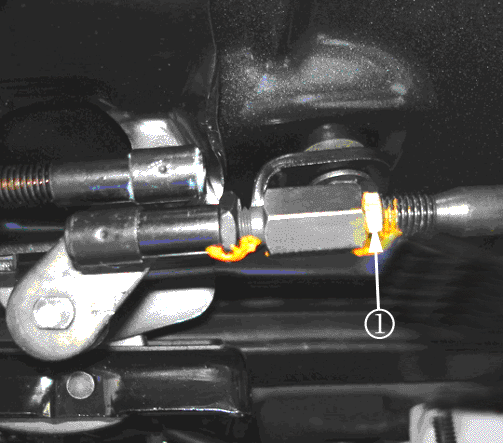
| • | If the hook does not activate the switch, loosen the nut (1) to shorten the rod. Shorten the rod by turning the turnbuckle toward the passenger side of the vehicle 1-2 turns. |
Claim Information
For vehicles repaired under this product enhancement, use:
Labor Operation | Description | Labor Time |
|---|---|---|
Y0093 | Inspect - No Further Action Req'd | 0.2 |
Y0094 | Inspect & Replace Latch Asm. | 0.7 |
