For 1990-2009 cars only
Removal Procedure
- Disconnect the negative battery cable. Refer to Battery Negative Cable Disconnection and Connection.
- Remove the air cleaner assembly. Refer to Air Cleaner Assembly Replacement.
- Remove the hood. Refer to Hood Replacement.
- Remove the intake manifold cover. Refer to Intake Manifold Cover Replacement.
- Remove the engine mount snubber and drive belt. Refer to Drive Belt Replacement.
- Remove the power steering pump and disconnect the power steering lines, if equipped. Refer to Power Steering Pump Replacement.
- Drain the cooling system. Refer to Cooling System Draining and Filling.
- Drain the engine oil. Refer to Engine Oil and Oil Filter Replacement.
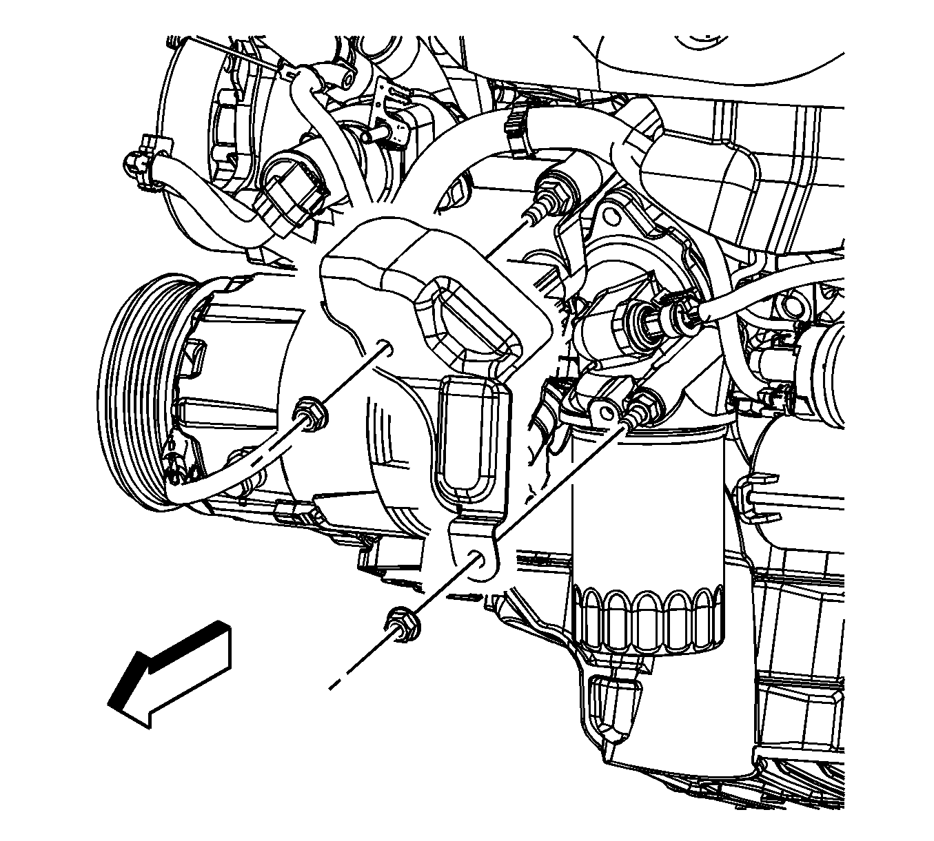
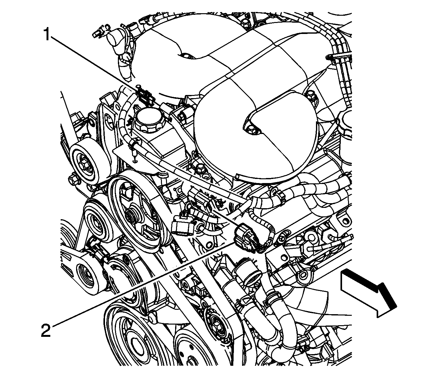
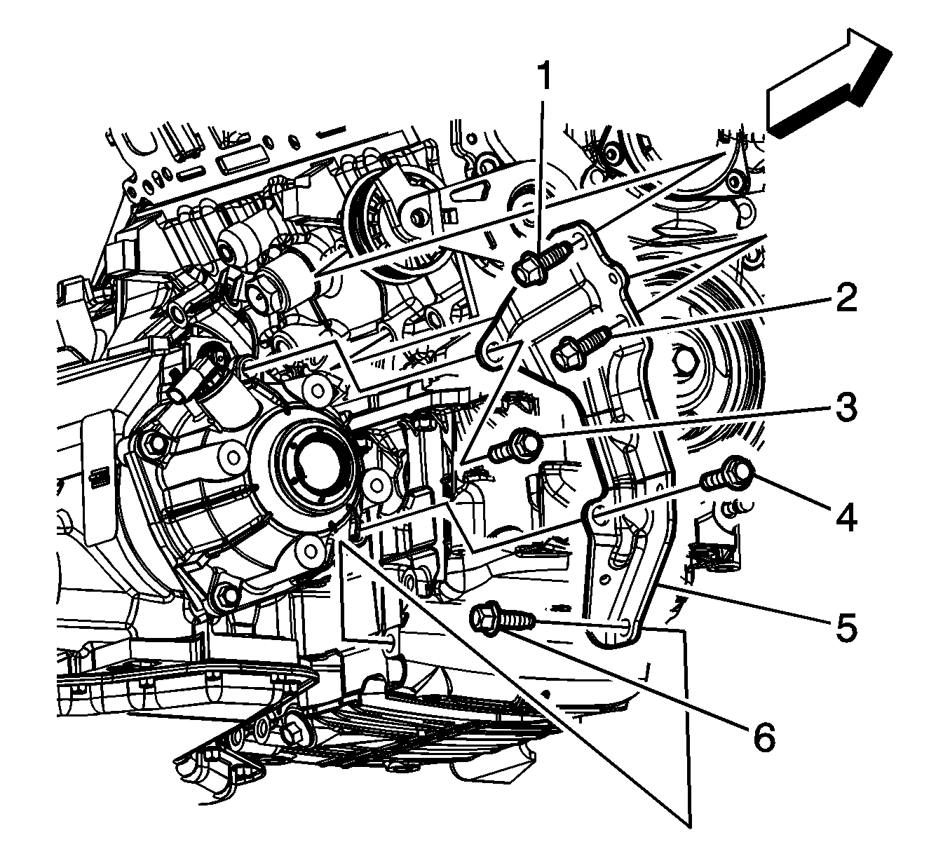
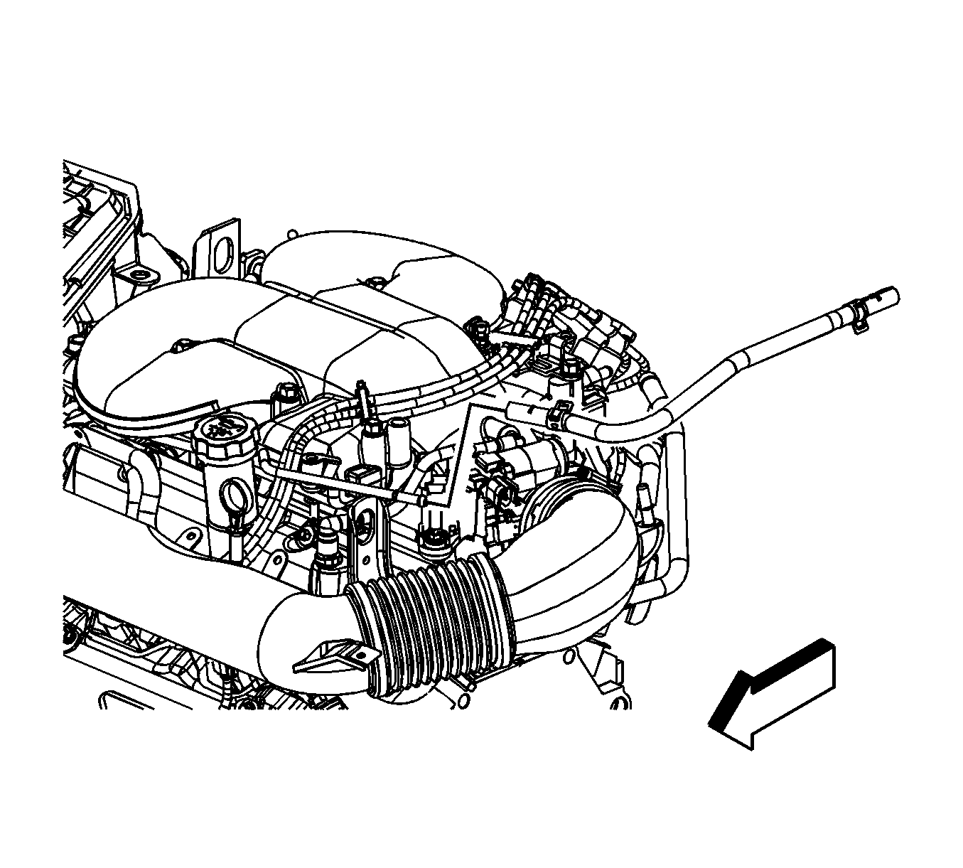
- Remove the oil pressure sensor heat shield nuts and shield.
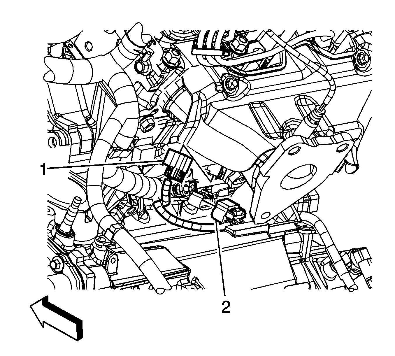
- Disconnect the oil pressure sensor (1) electrical connector.
- Disconnect the knock sensor (2) electrical connector.
- Disconnect the air conditioning (A/C) compressor electrical connector.
- Lower the vehicle.
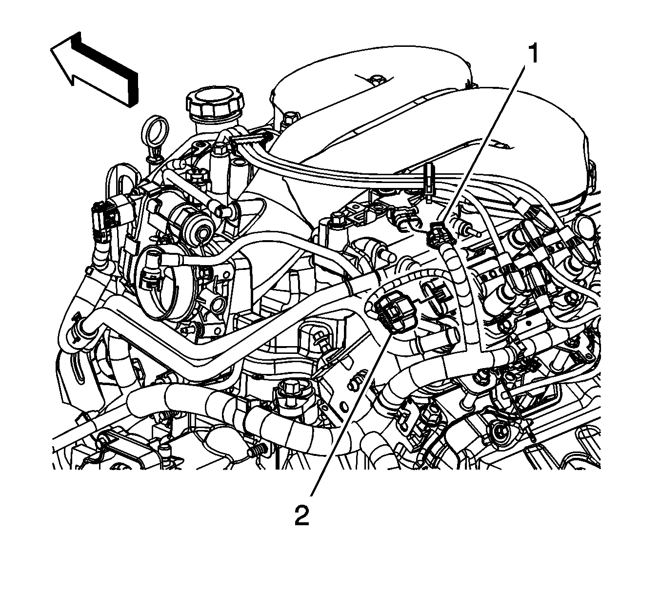
- Disconnect the evaporative emission (EVAP) canister purge solenoid (1) electrical connector.
- Disconnect the electronic throttle control (ETC) (2) electrical connector.
- Remove the connector position assurance (CPA) retainer (5).
- Disconnect the heated oxygen sensor (HO2S) (3) electrical connector.
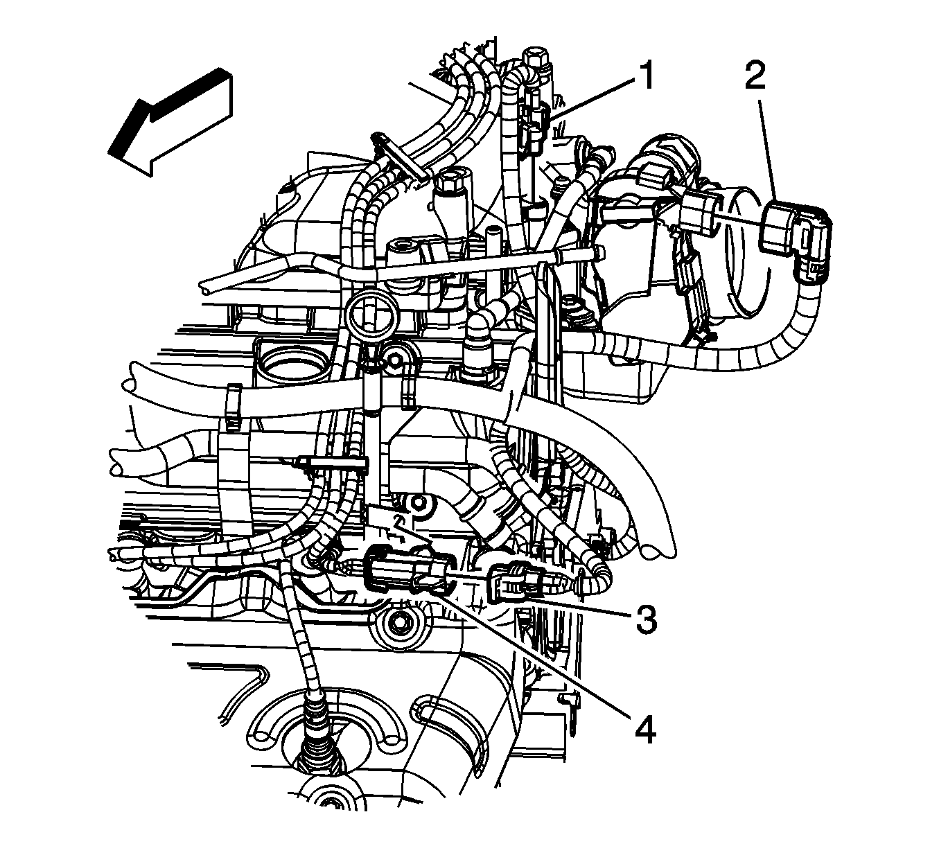
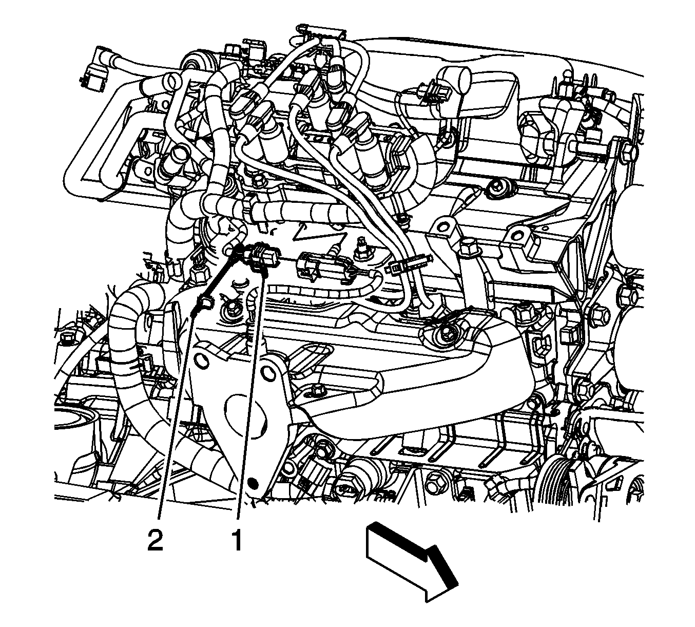
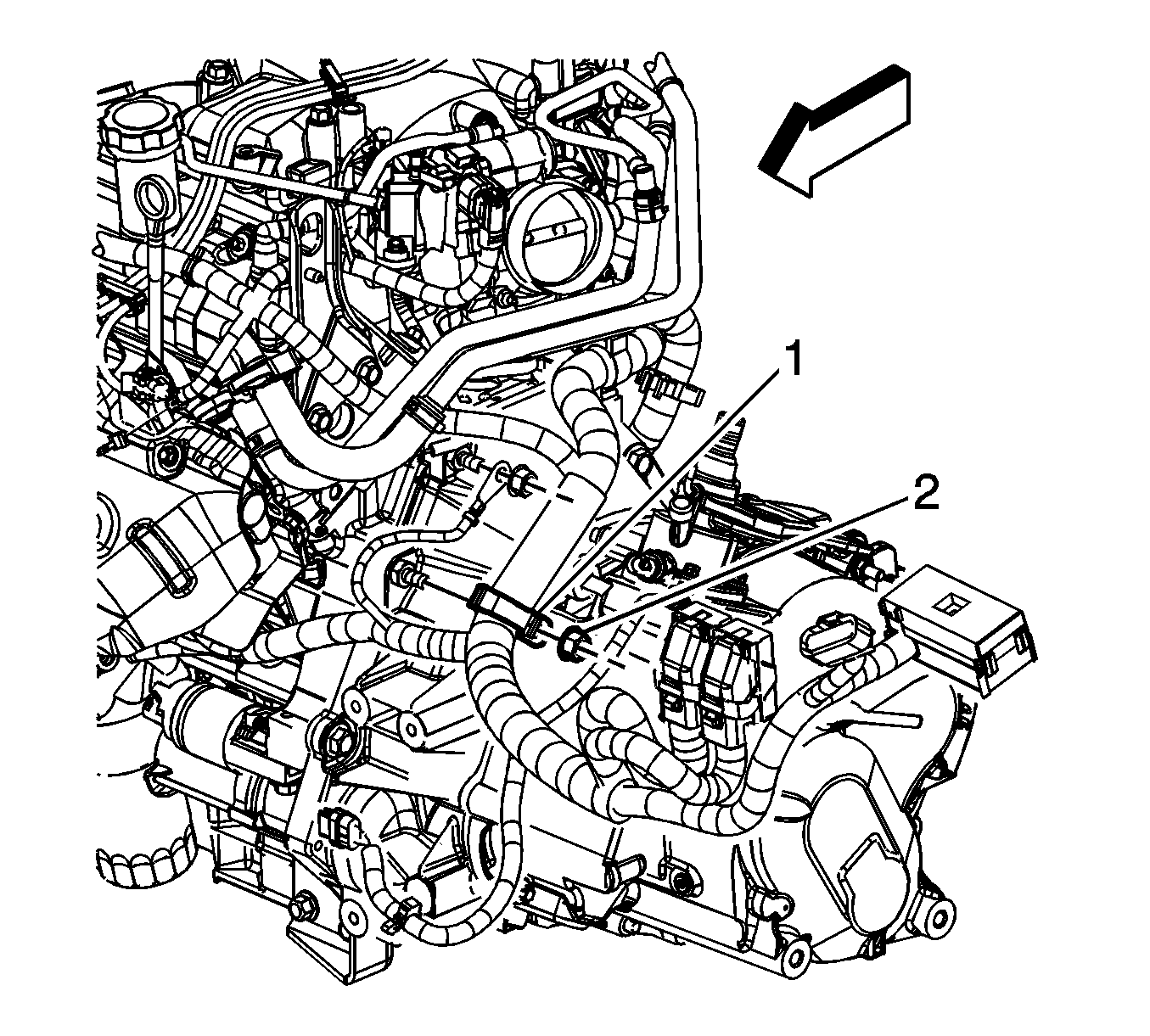
- Disconnect the manifold absolute pressure (MAP) sensor (1) electrical connector.
- Disconnect the ignition control module (2) electrical connector.
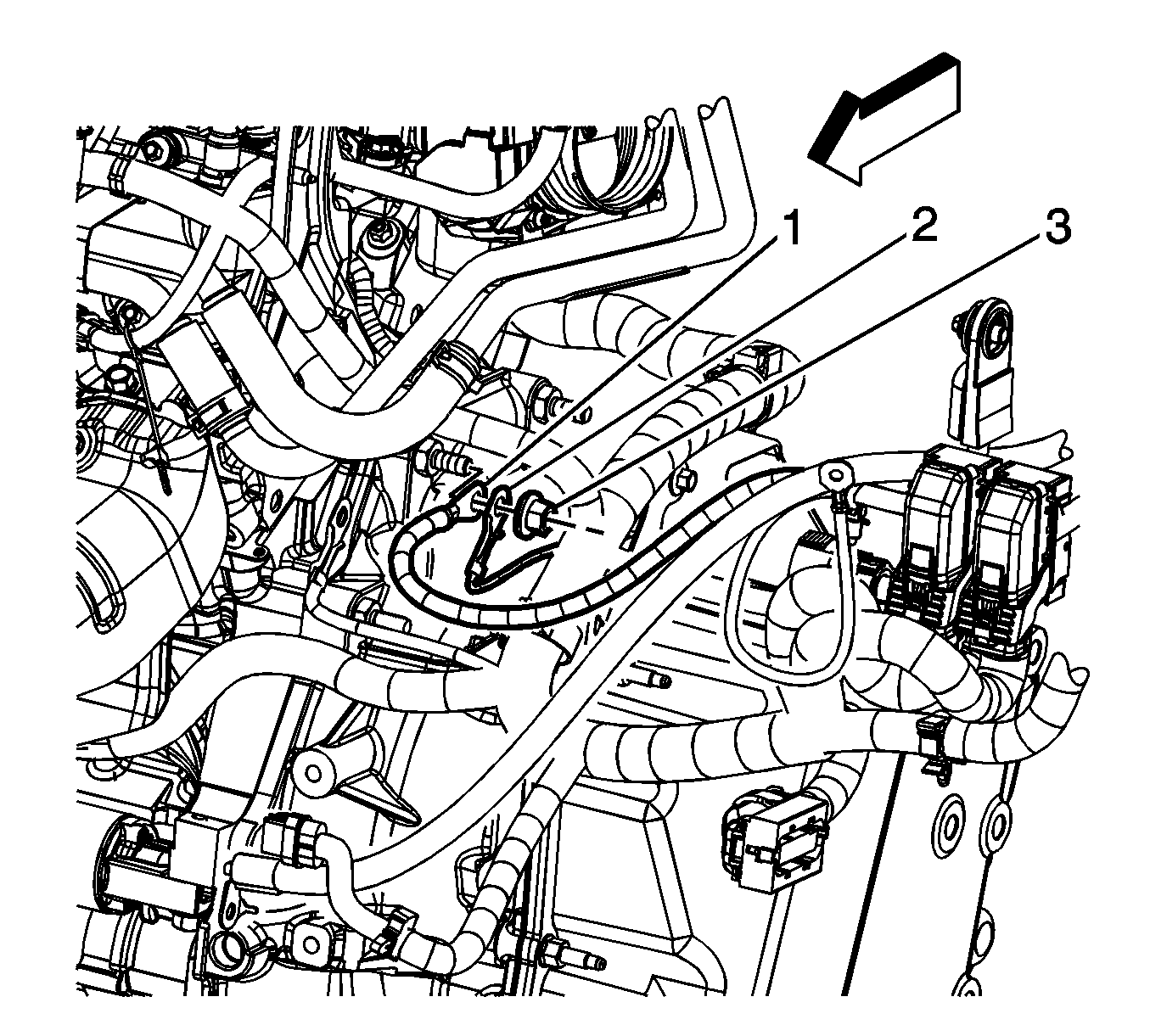
- Disconnect the inlet manifold valve (1) electrical connector.
- Disconnect the fuel injector inline (2) electrical connector.
- Disconnect the camshaft phasor sensor electrical connector.
- Remove the CPA retainer.
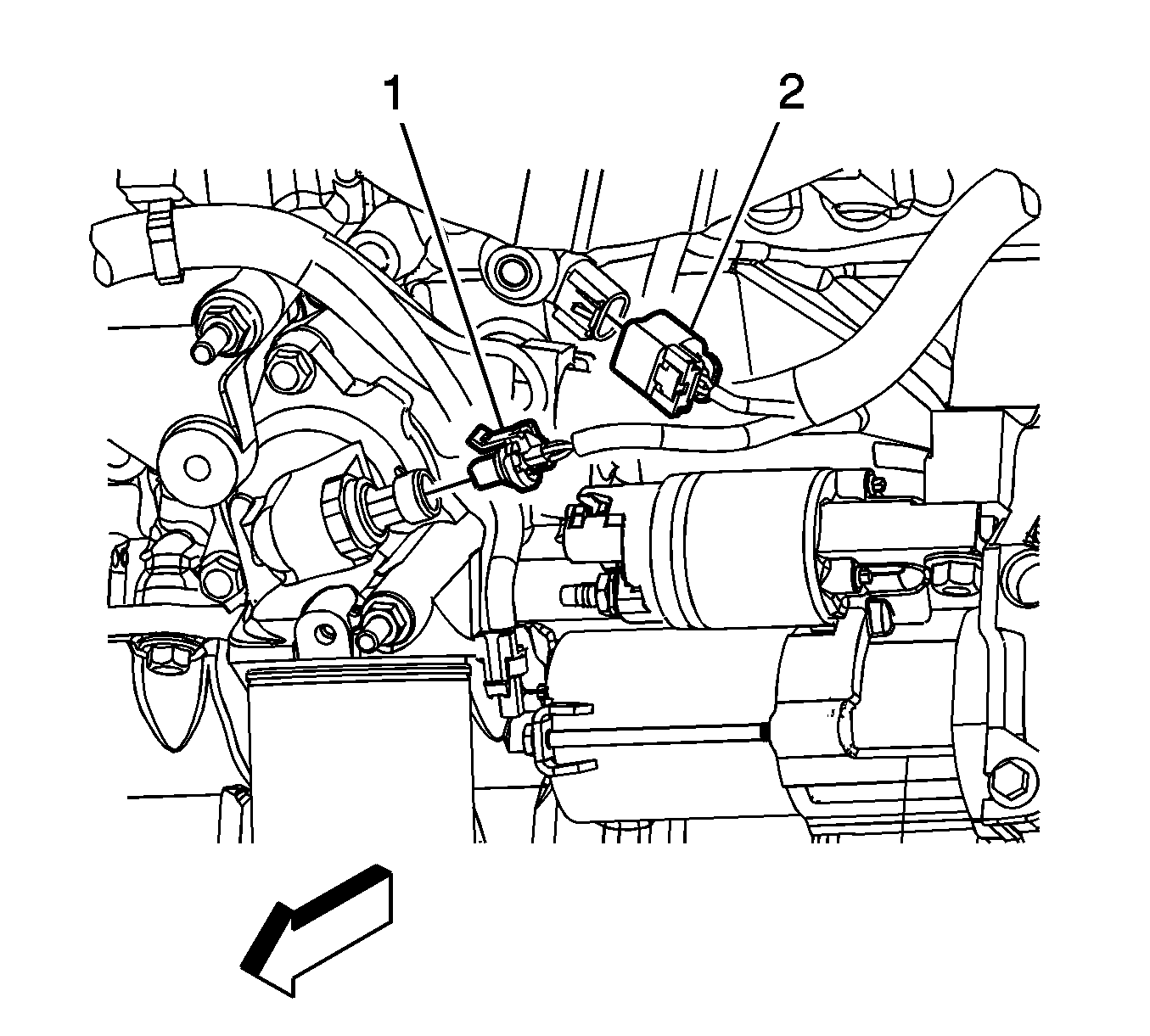
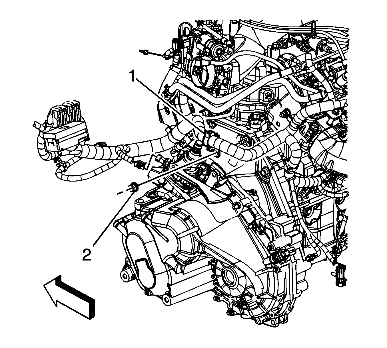
- Disconnect the rear upper HO2S electrical connector (1).
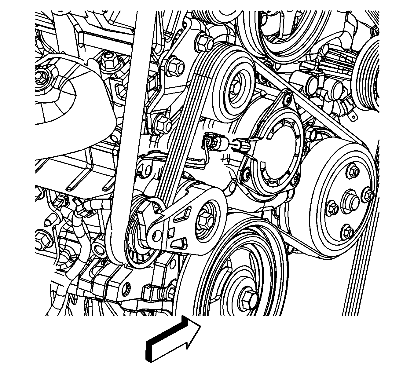
- Disconnect the knock sensor electrical connector (1).
- Disconnect the crankshaft position (CKP) sensor electrical connector (2).
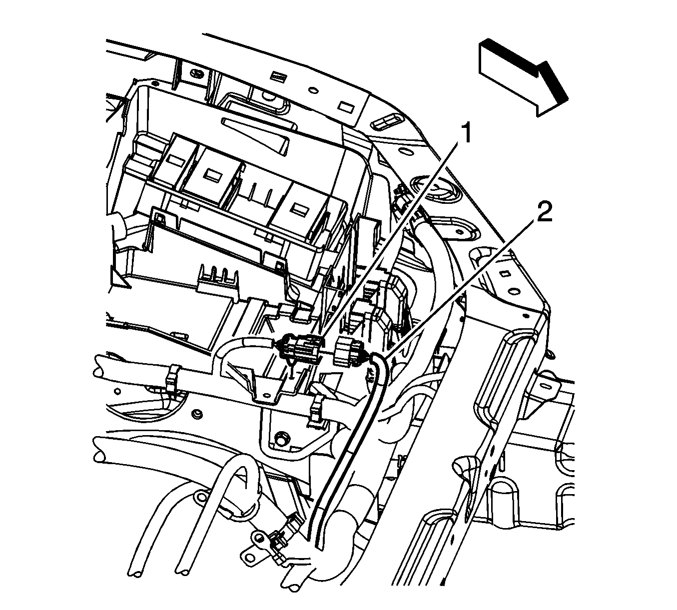
- Disconnect the engine harness connector (1) from the body harness connector (2).
- Disconnect the body harness electrical connector from the powertrain control module (PCM).
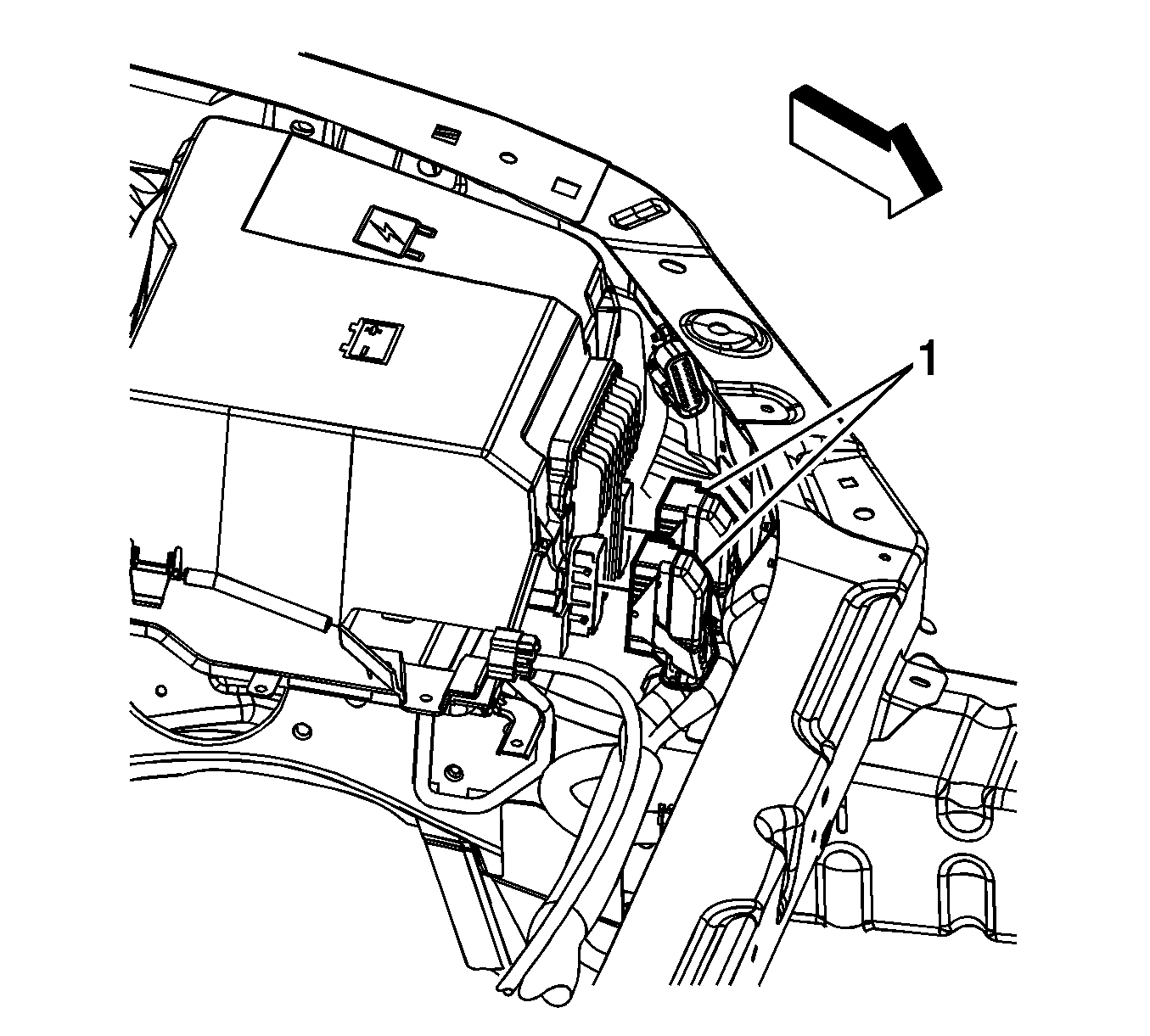
- Disconnect the engine harness electrical connectors (1) from the PCM.
- Disconnect the engine harness electrical connector from the transmission control module (TCM).
- Remove the engine harness clip nut (2).
- Remove the engine harness clip (1) from the transmission stud.
- Remove the engine harness ground nut (2).
- Remove the engine harness ground terminal (1) from the transmission stud.
- Remove the engine harness rear clip nut (2).
- Remove the engine harness rear clip (1) from the transmission stud.
- Remove the catalytic converters. Refer to Catalytic Converter Replacement - Left Side and Catalytic Converter Replacement - Right Side.
- Remove the engine mount. Refer to Engine Mount Replacement.
- Remove the torque converter cover. Refer to Torque Converter Cover Replacement.
- Remove the starter motor. Refer to Starter Motor Replacement.
- Remove the torque converter bolts. Refer to Flywheel to Torque Converter Bolt Replacement.
- Unbolt and reposition the A/C compressor to the side. DO NOT discharge the A/C system.
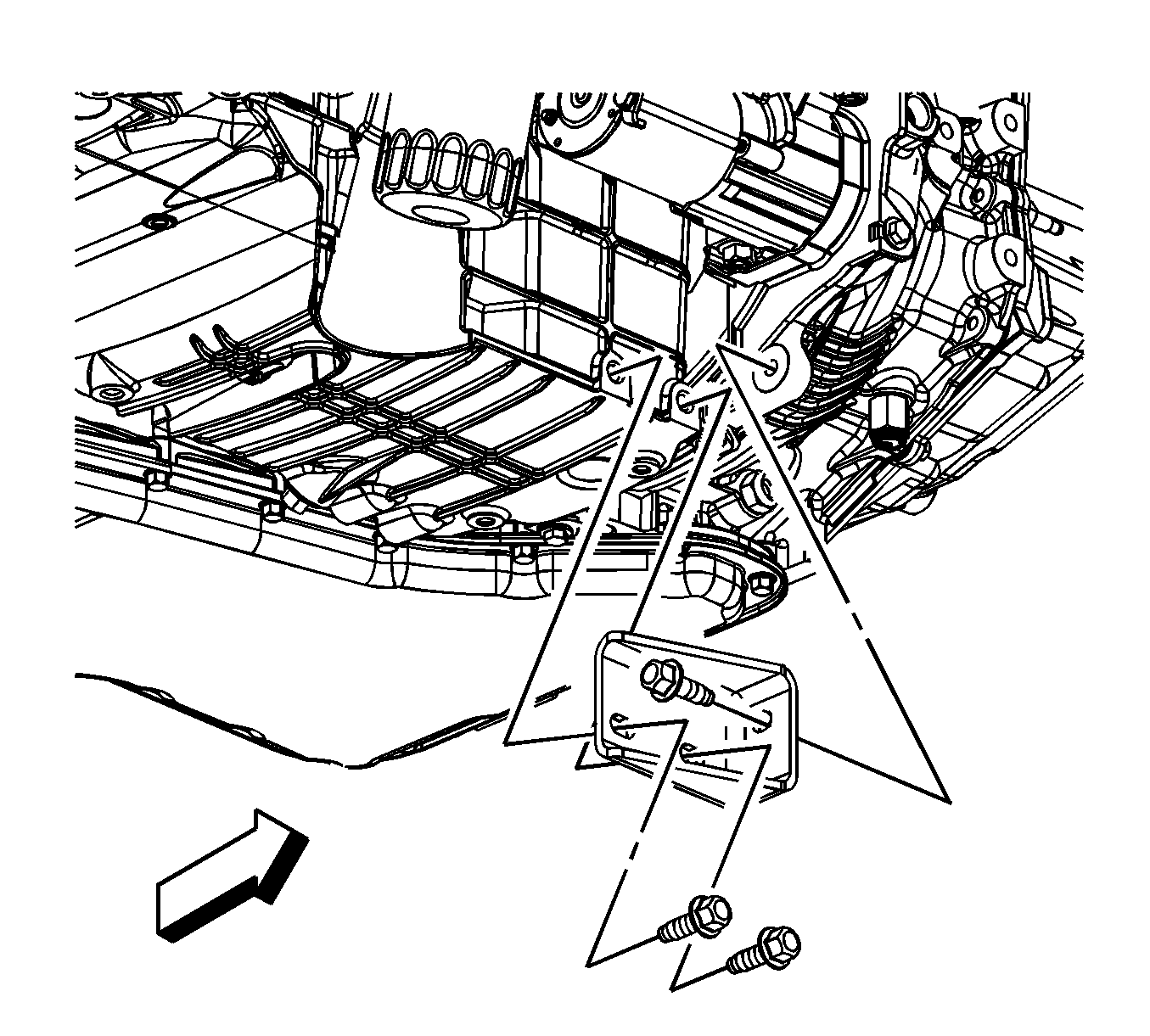
- Remove the transaxle brace to oil pan bolts.
- Remove the transaxle brace to transaxle bolt and remove the brace.
- Remove the transaxle brace to oil pan bolts, if equipped with regular production option (RPO) MT2.
- Remove the transaxle brace to transaxle bolt and remove the brace, if equipped with RPO MT2.
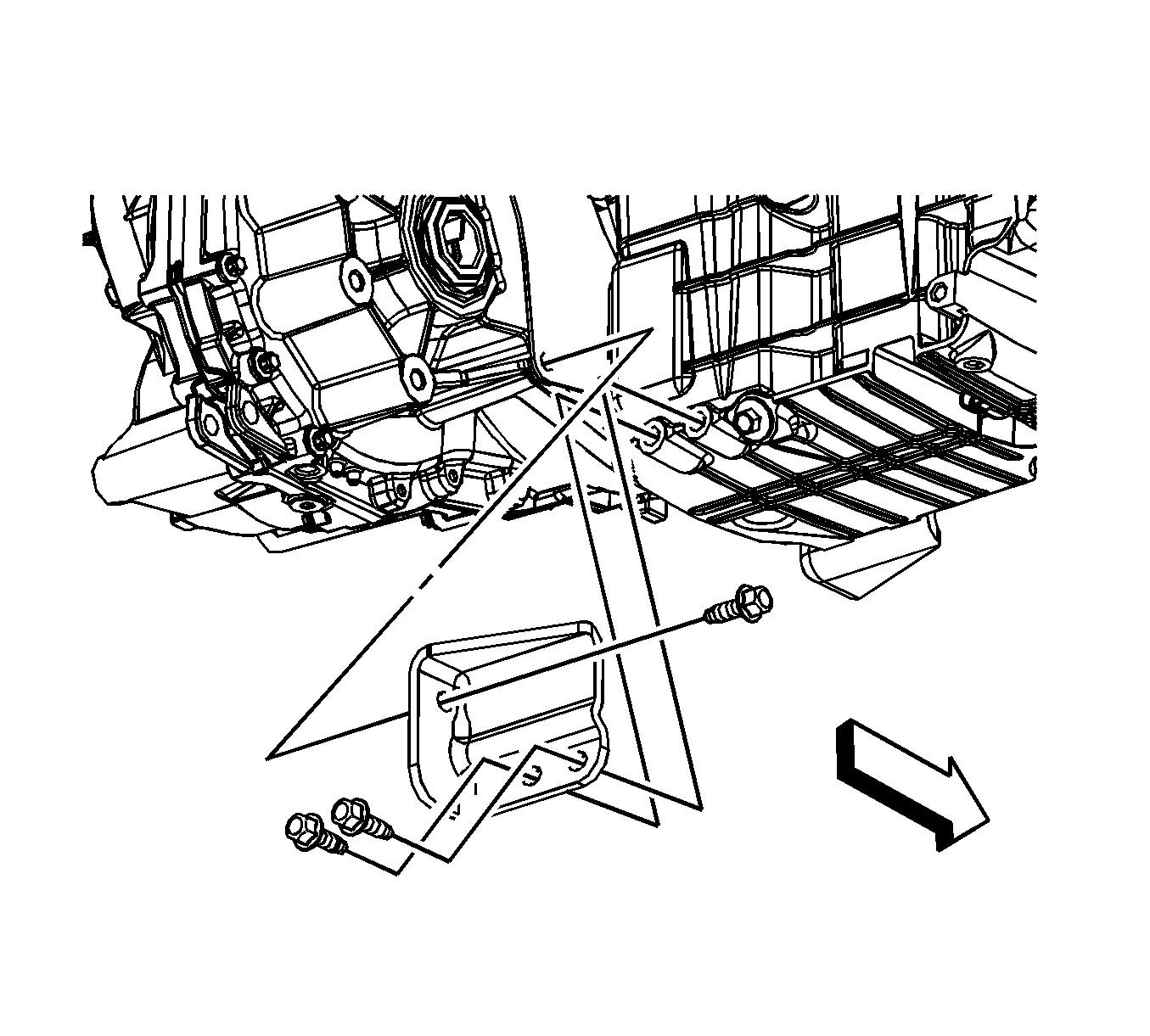
- Remove the transaxle brace to oil pan lower bolt (6), if equipped with RPO M15.
- Remove the lower transaxle-to-engine bolt and stud.
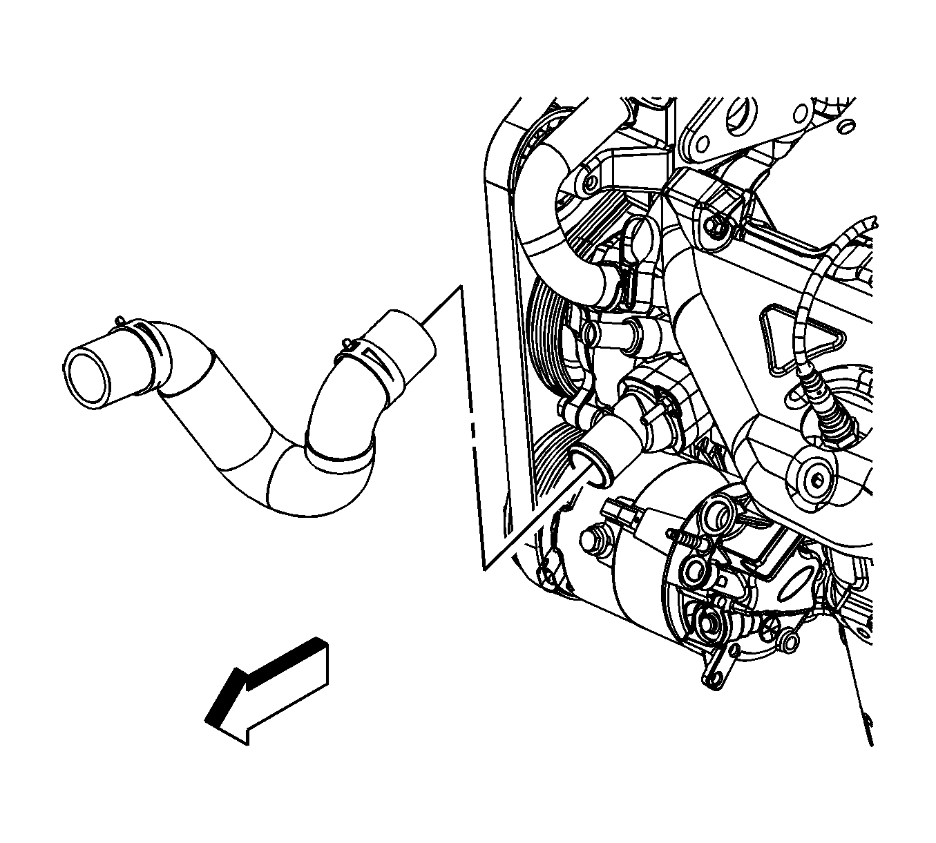
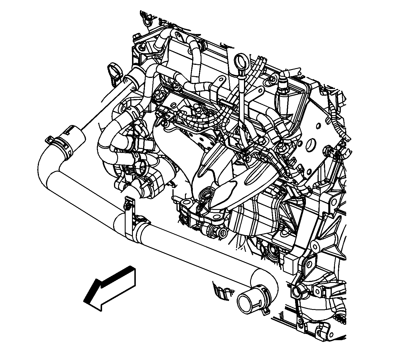
- Reposition the radiator outlet hose clamp at the thermostat housing.
- Remove the radiator outlet hose from the thermostat housing.
- Lower the vehicle and support the transaxle.
- Reposition the radiator surge tank hose clamp at the surge tank pipe.
- Remove the radiator surge tank hose from the surge tank pipe.
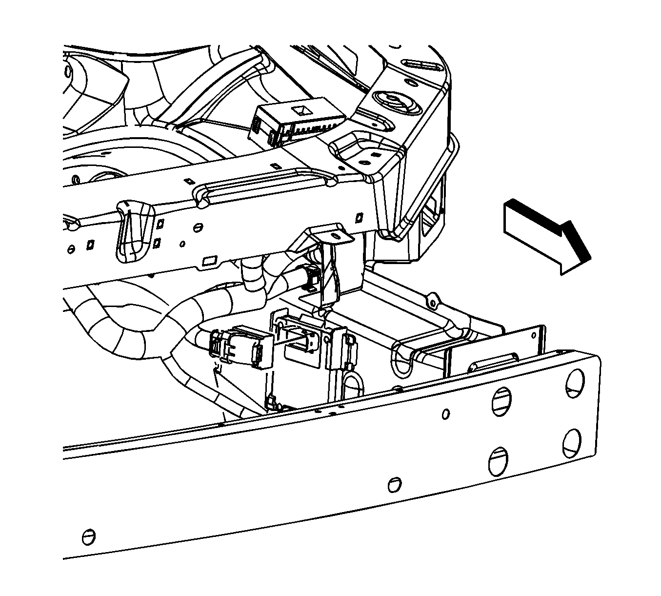
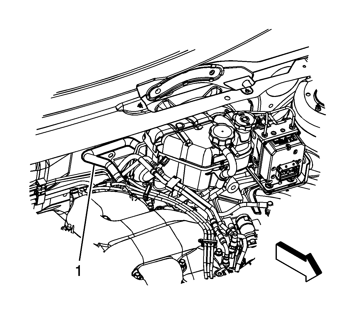
- Reposition the brake booster vacuum hose clamp at the intake manifold.
- Remove the brake booster vacuum hose (1) from the intake manifold.
- Reposition the heater inlet and outlet hose clamps at the engine.
- Remove the heater outlet and inlet hoses from the engine.
- Disconnect the fuel feed line from the fuel rail. Refer to Metal Collar Quick Connect Fitting Service.
- Disconnect the EVAP purge line from the canister purge solenoid. Refer to Plastic Collar Quick Connect Fitting Service.
- Reposition the radiator inlet hose clamp at the engine.
- Remove the radiator inlet hose from the engine.
- Install a engine lifting device to the engine.
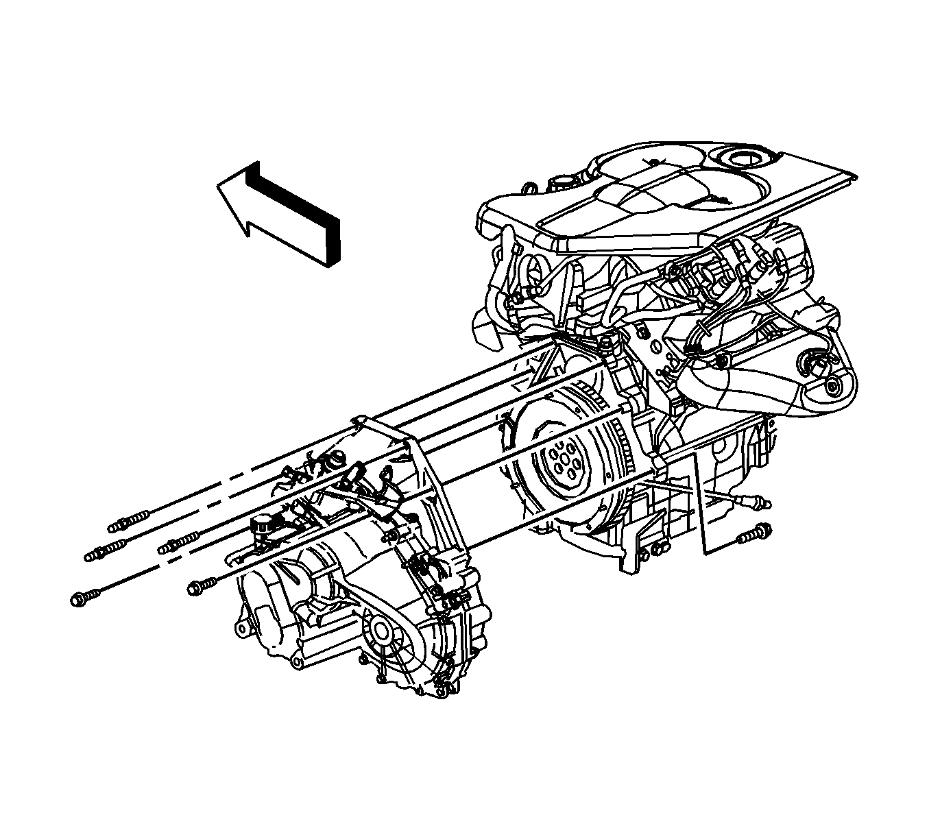
- Remove the remaining transaxle-to-engine bolts/studs if equipped with a manual transmission.
- Remove the remaining transaxle-to-engine bolts/studs if equipped with a automatic transmission.
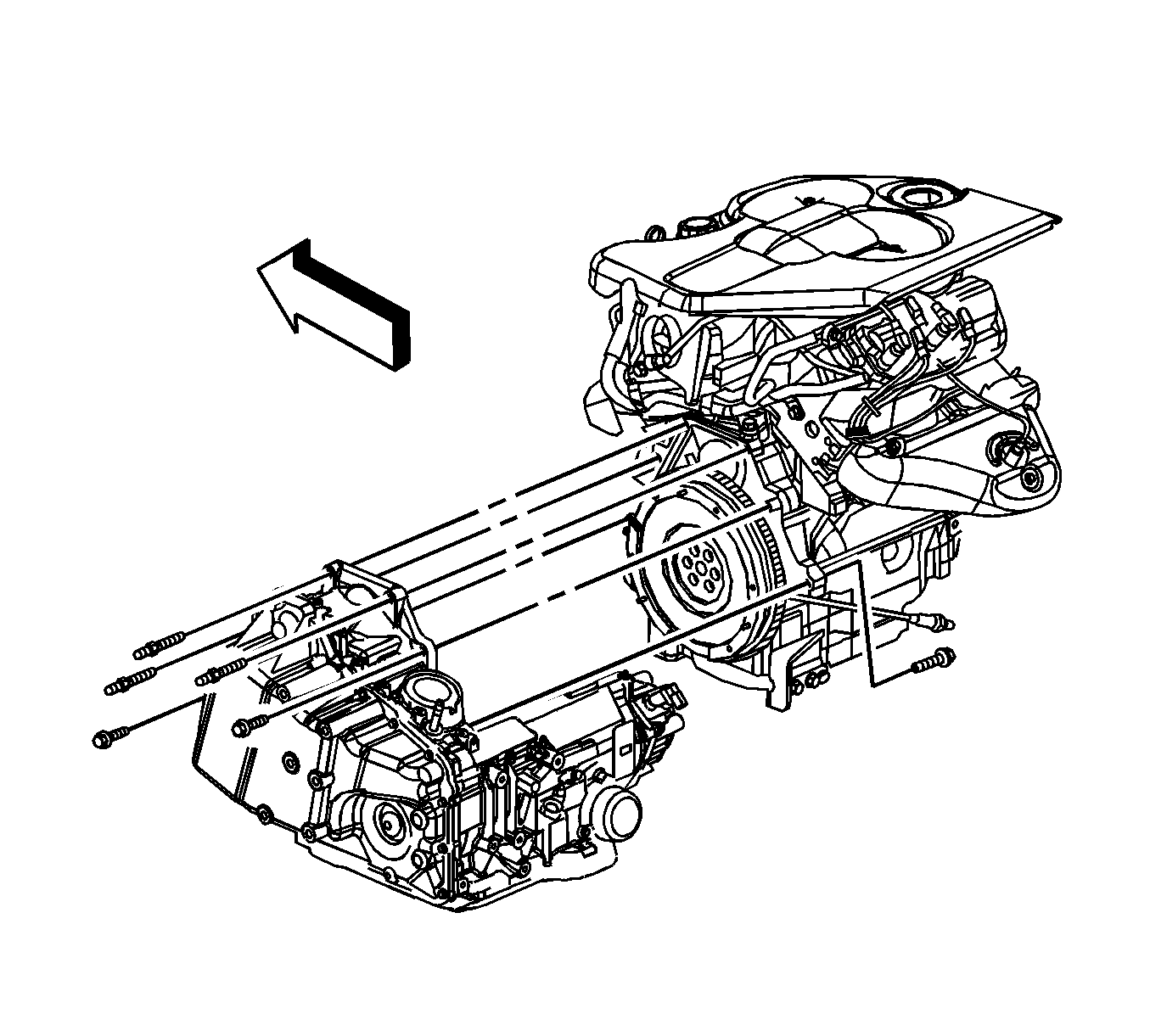
- Remove the engine from the vehicle.
- Remove the flywheel. Refer to Engine Flywheel Replacement.
- Install the engine to the engine stand.
Installation Procedure
- Install an engine lifting device to the engine.
- Remove the engine from the engine stand.
- Install the flywheel. Refer to Engine Flywheel Replacement.
- Install the engine to the vehicle.
- Install the transaxle-to-engine bolts/studs if equipped with a automatic transmission and tighten to 75 N·m (55 lb ft).
- Install the transaxle-to-engine bolts/studs if equipped with a manual transmission and tighten to 75 N·m (55 lb ft).
- Remove the engine lifting device from the engine.
- Install the radiator inlet hose to the engine.
- Position the radiator inlet hose clamp at the engine.
- Connect the EVAP purge line to the canister purge solenoid. Refer to Plastic Collar Quick Connect Fitting Service.
- Connect the fuel feed line to the fuel rail. Refer to Metal Collar Quick Connect Fitting Service.
- Install the heater outlet and inlet hoses to the engine.
- Position the heater inlet and outlet hose clamps at the engine.
- Install the brake booster vacuum hose (1) to the intake manifold.
- Position the brake booster vacuum hose clamp at the intake manifold.
- Install the radiator surge tank hose to the surge tank pipe.
- Position the radiator surge tank hose clamp at the surge tank pipe.
- Raise and support the vehicle.
- Install the radiator outlet hose to the thermostat housing.
- Position the radiator outlet hose clamp at the thermostat housing.
- Install the lower transaxle-to-engine bolt and stud and tighten to 75 N·m (55 lb ft).
- Install the transaxle brace to oil pan lower bolt (6), if equipped with RPO M15 and tighten to 50 N·m (37 lb ft).
- Position the transaxle brace and install the transaxle brace to transaxle bolt until snug, if equipped with RPO MT2.
- Install the transaxle brace to oil pan bolts, if equipped with RPO MT2 and tighten to 50 N·m (37 lb ft.
- Position the transaxle brace and install the transaxle brace to transaxle bolt until snug.
- Install the transaxle brace to oil pan bolts and tighten to 50 N·m (37 lb ft).
- Position and bolt up the A/C compressor and tighten the bolt to 50 N·m (37 lb ft).
- Install the torque converter bolts. Refer to Flywheel to Torque Converter Bolt Replacement.
- Install the starter motor. Refer to Starter Motor Replacement.
- Install the torque converter cover. Refer to Torque Converter Cover Replacement.
- Install the engine mount. Refer to Engine Mount Replacement.
- Install the catalytic converters. Refer to Catalytic Converter Replacement - Left Side and Catalytic Converter Replacement - Right Side.
- Install the engine harness rear clip (1) to the transmission stud.
- Install the engine harness rear clip nut (2) and tighten to 25 N·m (18 lb ft).
- Install the engine harness ground terminal (1) to the transmission stud.
- Install the engine harness ground nut (2) and tighten to 25 N·m (18 lb ft).
- Install the engine harness clip (1) to the transmission stud.
- Install the engine harness clip nut (2) and tighten to 25 N·m (18 lb ft).
- Connect the engine harness electrical connector to the TCM.
- Connect the engine harness electrical connectors (1) to the PCM.
- Connect the body harness electrical connector to the PCM.
- Connect the engine harness connector (1) to the body harness connector (2).
- Connect the CKP sensor electrical connector (2).
- Connect the knock sensor electrical connector (1).
- Connect the rear upper HO2S electrical connector (1).
- Install the CPA retainer.
- Connect the camshaft phasor sensor electrical connector.
- Connect the fuel injector inline (2) electrical connector.
- Connect the inlet manifold valve (1) electrical connector.
- Connect the ignition control module (2) electrical connector.
- Connect the MAP sensor (1) electrical connector.
- Connect the HO2S (3) electrical connector.
- Install the CPA retainer.
- Connect the ETC (2) electrical connector.
- Connect the EVAP canister purge solenoid (1) electrical connector.
- Raise and support the vehicle.
- Connect the A/C compressor electrical connector.
- Connect the knock sensor (2) electrical connector.
- Connect the oil pressure sensor (1) electrical connector.
- Install the oil pressure sensor heat shield and nuts and tighten the nuts to 25 N·m (18 lb ft).
- Lower the vehicle.
- Connect the power steering lines and install the power steering pump, if equipped. Refer to Power Steering Pump Replacement.
- Install the drive belt and engine mount snubber. Refer to Drive Belt Replacement.
- Install the intake manifold cover. Refer to Intake Manifold Cover Replacement.
- Install the hood. Refer to Hood Replacement.
- Install the air cleaner assembly. Refer to Air Cleaner Assembly Replacement.
- Fill the engine with oil. Refer to Engine Oil and Oil Filter Replacement.
- Fill the cooling system. Refer to Cooling System Draining and Filling.
- Connect the negative battery cable. Refer to Battery Negative Cable Disconnection and Connection.
- Inspect for leaks.
Caution: Refer to Fastener Caution in the Preface section.
