Removal Procedure
- Ignition OFF.
- Disconnect the battery negative cable. Refer to Battery Negative Cable Disconnection and Connection.
- Remove the fuel tank assembly. Refer to Fuel Tank Replacement.
- Remove the primary fuel tank module assembly from the fuel tank. Refer to Primary Fuel Tank Module Replacement.
- Remove the fuel level sensor from the primary fuel tank module assembly. Refer to Fuel Level Sensor Replacement.
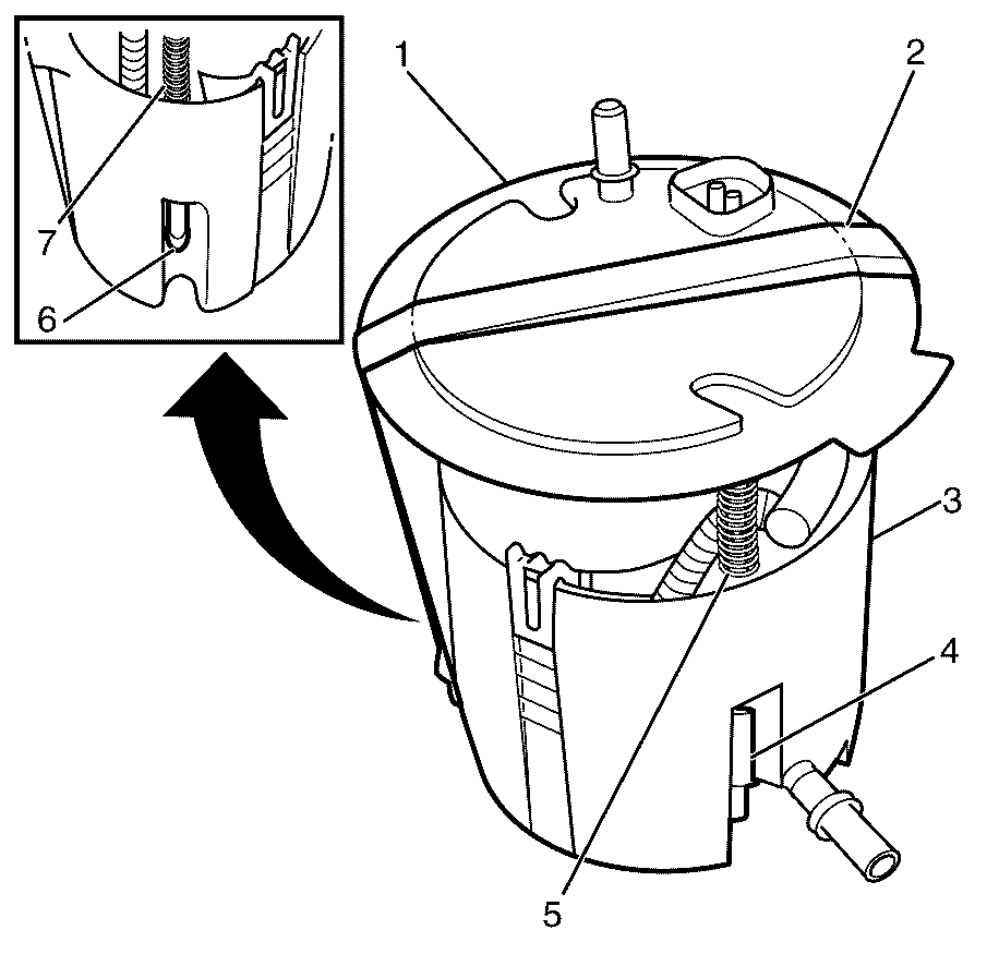
- Carefully compress the upper half (1) and lower half (3) of the primary fuel module assembly against the spring tension and secure the upper half (1) and lower half (3) together with suitable tape (2).
- Remove the retaining clip (4) from the primary fuel module upper half shaft (5) with a suitable tool.
- Remove the retaining clip (6) from the primary fuel module upper half shaft (7) with a suitable tool.
- Remove the tape used to secure the primary fuel module upper half (1) and the primary fuel module lower half (4) together.
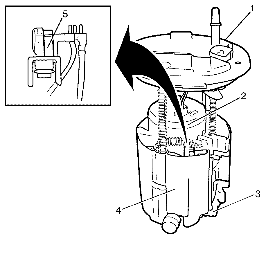
- Carefully separate the upper half (1) from the lower half (4) of the primary fuel module assembly.
- Detach the pipe connector (3) with a suitable tool.
- Detach the pipe connector (5) with a suitable tool.
- Carefully detach and remove the fuel pump housing (2) from the primary fuel module lower half (4).
- Detach the fuel filter (1) from the fuel pump housing (2) using a suitable tool.
Warning: Refer to Battery Disconnect Warning in the Preface section.
Warning: Refer to Gasoline/Gasoline Vapors Warning in the Preface section.
Warning: Refer to Safety Glasses Warning in the Preface section.
Danger: To avoid any vehicle damage, serious personal injury or death when major components are removed from the vehicle and the vehicle is supported by a hoist, support the vehicle with jack stands at the opposite end from which the components are being removed and strap the vehicle to the hoist.


Note: Take care when removing the tape used to secure the primary fuel module upper half (1) and the primary fuel module lower half (4) together. Failure to comply may result in personal injury.
Note: Observe the routing of the pipes.
Note: Do not damage the pipe connectors.

Installation Procedure
- Install the fuel filter (1) to the fuel pump housing (2).
- Carefully install the fuel pump housing (2) to the primary fuel module lower half (4).
- Attach the pipe connector (5) to the primary fuel module lower half (4).
- Attach the pipe connector (3) to the primary fuel module lower half (4).
- Carefully install the upper half (1) to the lower half (3) of the primary fuel module assembly.
- Carefully compress the upper half (1) and lower half (3) of the primary fuel module assembly against the spring tension and secure the upper half (1) and lower half (3) together with suitable tape (2).
- Install the retaining clip (4) to the primary fuel module upper half shaft (5).
- Install the retaining clip (6) to the primary fuel module upper half shaft (7).
- Remove the tape used to secure the primary fuel module upper half (1) and the primary fuel module lower half (3) together.
- Install the fuel level sensor to the primary fuel tank module assembly. Refer to Fuel Level Sensor Replacement.
- Install the primary fuel tank module assembly to the fuel tank assembly. Refer to Primary Fuel Tank Module Replacement.
- Install the fuel tank assembly. Refer to Fuel Tank Replacement.
- Connect the battery negative cable. Refer to Battery Negative Cable Disconnection and Connection.

Note: Listen for audible clicks to confirm correct installation of the fuel filter (1) to the fuel pump housing (2).
Note: Make sure that all the retainers of the fuel filter (1) engages the fuel pump housing (2).

Note: Observe the routing of the pipes.
Note: Do not damage the pipe connectors.
Note: Listen for audible clicks to confirm correct installation of the fuel pump housing (2) to the primary fuel module lower half (4).
Note: Make sure that all the retainers of the fuel pump housing (2) engages the primary fuel module lower half (4).
Note: Listen for an audible click to confirm correct installation of the connector (5) to the primary fuel module lower half (4).
Note: Listen for an audible click to confirm correct installation of the connector (3).

