For 1990-2009 cars only
Tools Required
J 45059 Angle Meter
CH-46839 Rear Crossmember Centering Tool
Removal Procedure
- Raise and support the vehicle. Refer to Lifting and Jacking the Vehicle in General Information.
- Remove the rear exhaust system. Refer to Muffler Replacement in Engine Exhaust.
- Remove the propeller shaft. Refer to Two-Piece Propeller Shaft Replacement in Propeller Shaft.
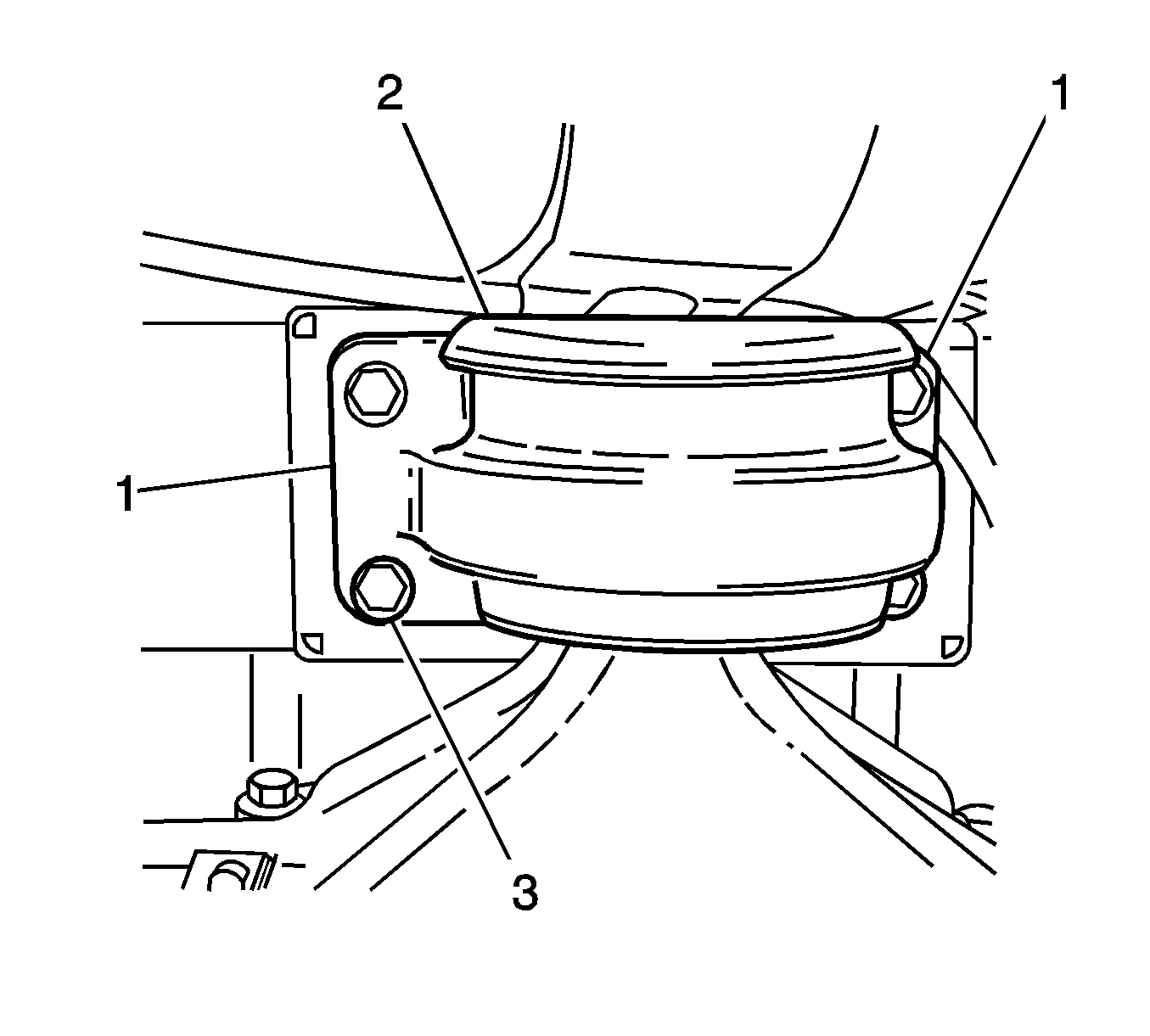
- Using a scribe, mark the rear mount (2) to the vehicle under body location (1), this will assist in the rear suspension support alignment on installation.
- Support the differential carrier.
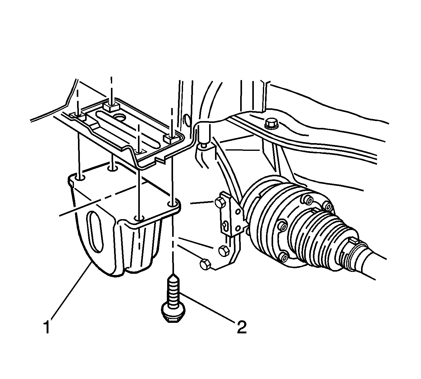
- Remove the rear mount (1) to underbody bolts (2) and discard.
- Lower the differential carrier and rear suspension crossmember at least 60 mm (2.4 in).
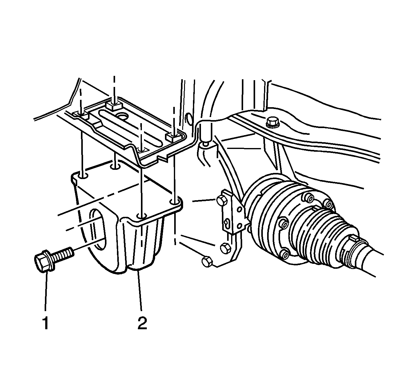
- Remove the rear mount to (2) differential carrier cover bolts (1) and discard.
- Remove the rear mount.
Installation Procedure
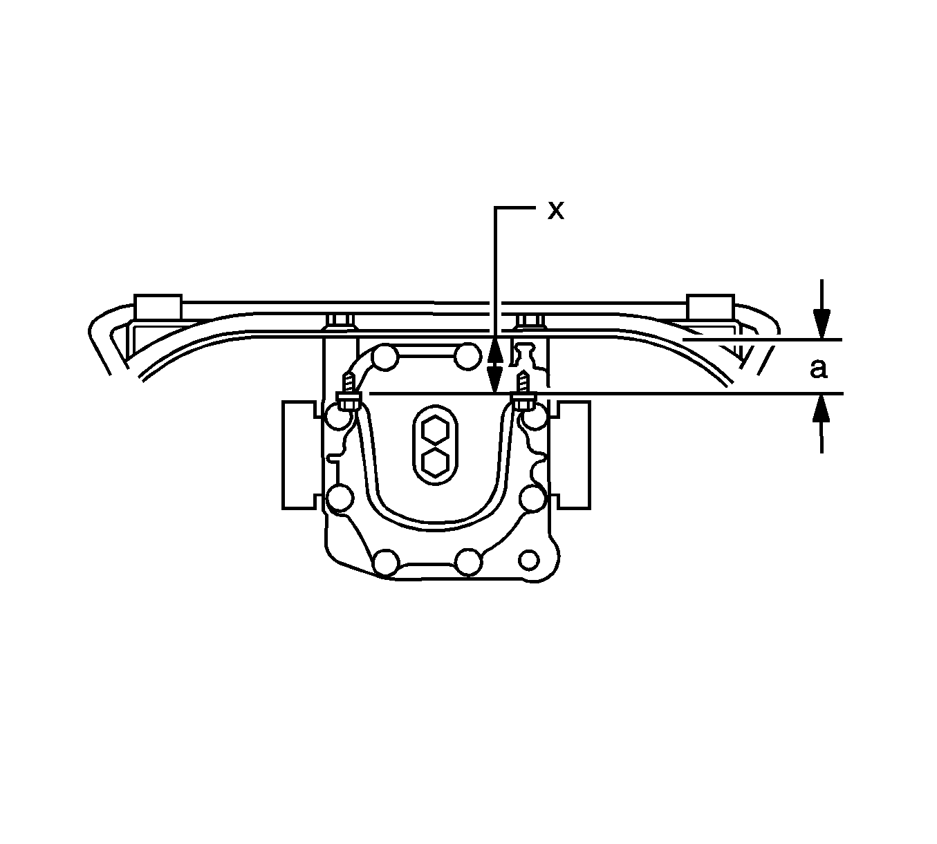
- When tightening the mount bolts, ensure the mount does not twist. The mount should remain parallel (X) with the rear suspension support.
- Using new bolts, (1) install the rear mount (2) to the differential carrier cover.
- Tighten the rear mount to differential carrier cover bolts (1).
- Raise the differential until it contacts the underbody.
- Align the marks (1) and install the rear mount (2) to underbody bolts (3) finger tight.
- Fit the CH-46839 to the underbody.
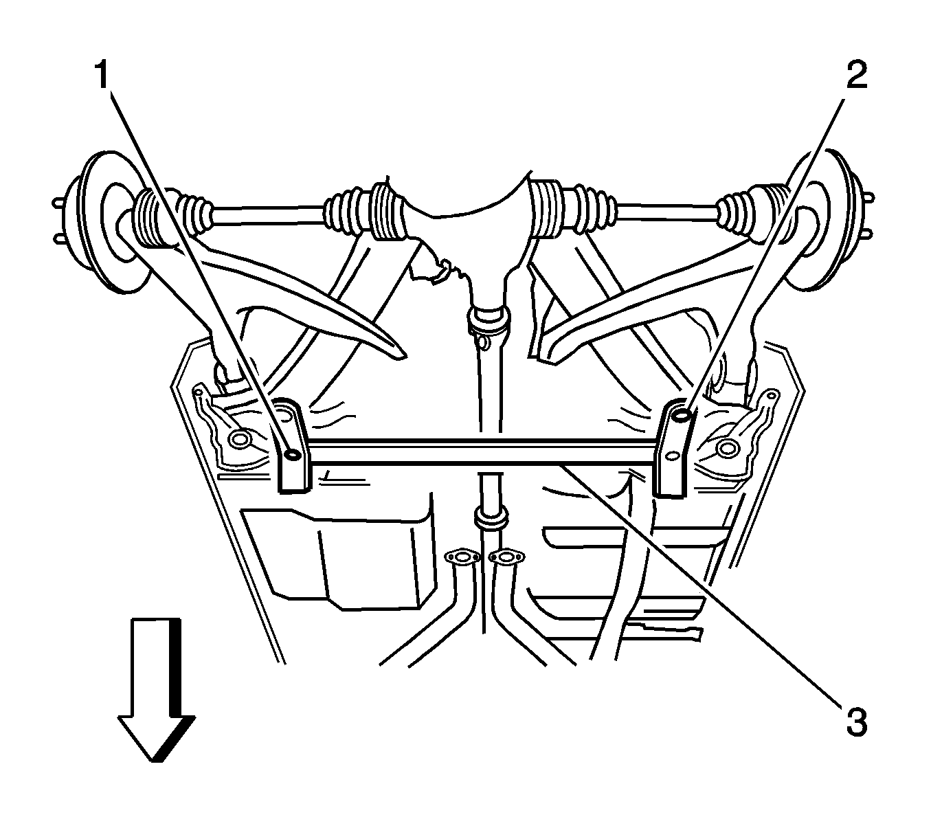
- The rear crossmember centering tool (3) locates into 19 mm (0.74 in) diameter body datum holes (1) positioned forward of the rear suspension support.
- With the aid of an assistant position the rear crossmember centering tool (3) location pins (2) to engage the alignment holes on the rear suspension support assembly.
- If the alignment holes on the rear suspension do not align with the crossmember centering tool location pins, the crossmember must be aligned. To align the crossmember, refer to Rear Support Replacement in Frame and Underbody.
- With the marks aligned (1), tighten the rear mount (2) to underbody bolts (3).
- Tighten mount bolts to 90 N·m (66 lb ft).
- Using the J 45059 , apply an additional 60 degrees of torque
- Install the propeller shaft . Refer to Two-Piece Propeller Shaft Replacement in Propeller Shaft.
- Install the rear exhaust system. Refer Muffler Replacement in Engine Exhaust.
- Lower the vehicle. Refer to Lifting and Jacking the Vehicle in General Information.
Notice: Refer to Fastener Notice in the Preface section.

Tighten
Tighten the bolts to 95 N·m (70 lb ft).

Important: Ensure the underbody and the rear mount are parallel. Dimension (a) should be 56.7 mm (2.2 in).

Tighten
